- Catalogs
- RAE Systems
- Miller ShockFusion™ End/Corner Roof Posts and Miller Fusion™ Intermediate Roof Posts
Miller ShockFusion™ End/Corner Roof Posts and Miller Fusion™ Intermediate Roof Posts
1 /4Pages

Miller ShockFusion™ End/Corner Roof Posts and Miller Fusion™ Intermediate Roof Posts
1 /4Pages
Catalog excerpts

Miller ShockFusion™ End/Corner Roof Posts and Miller Fusion™ Intermediate Roof Posts Description Miller ShockFusion Horizontal Lifeline Roof Systems are available in custom-engineered systems and straight-line system kits. Miller ShockFusion and Fusion Roof Posts lower force applied to the base and/or complete horizontal lifeline system. This spec sheet addresses the roof posts--ShockFusion End/Corner Roof Posts and Fusion Intermediate Roof Posts*. Spec sheets for other system components are available: Miller ShockFusion Base Plates and Mounting Assemblies (SP453) Miller ShockFusion Cable Assembly Components (SP485) Miller ShockFusion Energy Absorber: Internal Connecting Components: Post Tube: Post/Base Plate Seal: Post Cap: Miller Fusion Energy Absorber: Internal Connecting Components: Post Tube: Post/Base Plate Seal: Post Cap: X11009 - Miller ShockFusion End/Corner Roof Post 304 Stainless Steel 304 and 18-8 Stainless Steel Zinc-Plated/Powder Coated Steel; Anodized Cast 6061-T6 Aluminum HDPE and Neoprene HDPE with UV Inhibitor X11008 - Miller Fusion Intermediate Roof Post* 304 and 18-8 Stainless Steel Zinc-Plated/Powder Coated Steel; Anodized Cast 6061-T6 Aluminum HDPE and Neoprene Vinyl with UV Inhibitor Ø4.12in [105mm] Miller ShockFusion Activation Force: 1,100 lbs. (4.89 kN) Shock Absorption Force: 2,500 lbs. (11.1 kN) Maximum Capacity: See ShockFusion Instruction Manual Ultimate Strength: 5,000 lbs. (22.2 kN) Miller Fusion Activation Force: Maximum Capacity: Ultimate Strength: 1,000 lbs. (4.4 kN) See Fusion and/or ShockFusion Instruction Manual(s) 5,000 lbs. (22.2 kN) All system components meet the design requirements as set forth in OSHA 1926.502, OSHA 1910.66, ANSI A10.32-04, ANSI Z359.6, CSAZ259.16-2004 and EN795 Class C. Please note, however, that the system as a whole once installed must be deemed to be in compliance with these standards by a qualified engineer. [*Note: The Miller Fusion Roof Post may also be used used as a single anchorage point for a personal fall arrest system when the D-bolt anchor is attached. See Fusion Instruction Manua
Open the catalog to page 1
Miller ShockFusion™ End/Corner Roof Posts and Miller Fusion™ Intermediate Roof Posts An engineer or qualified person must ensure that the roof structure to which a ShockFusion System is installed is able to withstand potential tensile and shear forces which may be imposed at the locations where end and intermediate roof anchor posts are attached. The tensile and shear strength requirements are based on a 2:1 safety factor. ShockFusion Roof Post Distribution of Tensile Forces to Hardware 1250 Actual Tensile Force Fastener Tensile Strength Requirement (# Per Corner) Tensile Strength Required with...
Open the catalog to page 2
Miller ShockFusion™ End/Corner Roof Posts and Miller Fusion™ Intermediate Roof Posts Fusion Roof Post Distribution of Tensile Forces to Hardware 1250 Actual Tensile Force Fastener Tensile Strength Requirement (# Per Corner) Tensile Strength Required with 2x Safety Factor A: Post Tipping Point: Tensile Force Peak B: 1800# Applied Tipped Post Loading Begins 0 0 Pounds Force Applied to Top of Post Tensile Force Distribution at Intermediate Posts • Maximum tensile force at intermediate posts is 500# per corner of base plate; tensile strength required is 1000# with a 2:1 safety factor incorporated
Open the catalog to page 3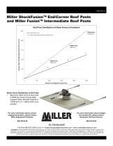
Miller ShockFusion™ End/Corner Roof Posts and Miller Fusion™ Intermediate Roof Posts Roof Post Distribution of Shear Forces to Hardware 1250 Actual Shear Force Fastener Shear Strength Requirement (# Per Corner) Shear Strength Required with 2x Safety Factor Pounds Force Applied to Top of Post Shear Force Distribution at All Posts • Maximum shear force at each post is 625# per corner of base plate; required shear strength required is 1250# with a 2:1 safety factor incorporated For more information about customengineered systems, please contact Miller Engineered Solutions: For more information about...
Open the catalog to page 4All RAE Systems catalogs and technical brochures
 HAND & ARM PROTECTION
12 Pages
 Miller TechLine™ Kits
2 Pages
 Miller DuraHoistTM
8 Pages
 Miller ®
4 Pages
 FALL PROTECTION
22 Pages
 Miller H500 Series
8 Pages
 HONEYWELL RIG DOG™ GLOVES
12 Pages
 AreaRAE Pro
8 Pages
 RAELink3 Mesh
2 Pages
 RAEShare
1 Page
 RDK Rugged- Host
2 Pages
 SensorRAE 4R+
2 Pages
 Smoke Generation Tubes
1 Page
 SolarRAE
2 Pages
 ToxiRAE Pro CO2
2 Pages
 ToxiRAE Pro
2 Pages
 ToxiRAE Pro LEL
2 Pages
 ToxiRAE Pro PID
2 Pages
 UltraRAE 3000
2 Pages
 VOC Zeroing Tube
2 Pages
 WeatherPak
2 Pages
 Humidity Filtering II Tube
2 Pages
 MBeacon
2 Pages
 Wireless Alarm Bar
2 Pages
 MicroRAE
5 Pages
 MultiRAE Benzene
2 Pages
 MeshGuard
2 Pages
 AreaRAE Steel Z1
2 Pages
 AreaRAE Gamma Steel
2 Pages
 EchoView Host
2 Pages
 FMC-2 and FMC-4
2 Pages
 FMC-16
2 Pages
 FMC 2000
2 Pages
 EntryRAE
2 Pages
 miniDOSE
2 Pages
 DoseRAE Pro
2 Pages
 QRAE 3
2 Pages
 RAEGuard LEL
2 Pages
 RAEGuard PID
2 Pages
 RAE Systems
35 Pages
 BioHarness
2 Pages
 AutoRAE Lite for ToxiRAE 3
2 Pages
 AutoRAE Lite for QRAE II
2 Pages
 AreaRAE Steel Z2
2 Pages
 MiniRAE Lite Datasheet
2 Pages
 GammaRAE II R
2 Pages
 FMC-60
2 Pages
 FMC-40
2 Pages
 FMC-10
2 Pages
 ChemRAE
2 Pages
 AutoRAE 2
2 Pages
 AreaRAE Inert
2 Pages
 QRAE Plus
2 Pages
 QRAE II Pump
2 Pages
 QRAE II Diffusion
2 Pages
 ProRAE Guardian
2 Pages
 PlumeRAE
2 Pages
 NeutronRAE II
2 Pages
 MultiRAE Pro
2 Pages
 MultiRAE Lite
2 Pages
 MultiRAE
2 Pages
 MiniRAE Lite
2 Pages
 MiniRAE 3000
2 Pages
 DoseRAE
2 Pages


Archived catalogs
 AreaRAE Gamma Steel
2 Pages
 EchoView Host
2 Pages
 ppbRAE 3000
2 Pages
 2010 RAE Systems Mini Catalogue
23 Pages
 HazRAE
2 Pages
 ToxiRAE 3 Datasheet
2 Pages
 Benzene - The Next Asbestos?
5 Pages


- Shoes
- Fabric clothing
- Mechanical protection protection gloves
- Anti-slip safety shoes
- Electrical protection safety shoes
- Work safety gloves
- Gas detector
- Industrial safety gloves
- Anti-static safety shoes
- 10 protection gloves
- 9 protection gloves
- 8 protection gloves
- EN 388 safety gloves
- Chemical protection safety gloves
- Handling protection gloves
- Work coveralls
- Industrial detector
- Plastic glove
- Thermal protection clothing
- 7 protection gloves