VX2M
1 /9Pages

VX2M
1 /9Pages
Catalog excerpts

Issue 1, 05 February 2019 VX2M -NBFM Vibration resistant Category 1 Multi-channel Transceiver VX2M is a 400MHz band transceiver conforming to the Radiometrix TR2M pinout. It uses a sophisticated combination of techniques to produce a very robust device with excellent resistance to vibration. It meets the ETSI Category 1 high performance receiver specification to be used where the operation of a SRD may have inherent safety of human life implications. It retains all the pin-functions of the parent TR2M (including noise operated squelch/carrier detect and separate digital/analogue inputs and outputs). It also supports the same internal i1200 modem as the TR2M. Figure 1: VX2M-458-5 Conforms to EN 300 220-3 and EN 301 489-3 ETSI EN 300 220-1 Category 1 High performance level receiver Any 3MHz band module from 400MHz to 475MHz available as factory tuned custom variant High performance double superhet, 128 channel PLL Synthesizer with TCXO Data rates up to 5 kbps for standard module Usable range over 1km (with 100mW variant) Fully screened Feature-rich interface (RSSI, automatic noise squelch, analogue and digital baseband) Incorporates a 1200baud dumb modem User configurable via RS232 interface Handheld terminals Heavy vehicle/machine remote controls EPOS equipment, barcode scanners Data loggers Industrial telemetry and telecommand In-building environmental monitoring and control High-end security and fire alarms Vehicle data up/download Operating frequency: 458.5-459.1MHz or 433.05-434.79MHz Custom variants from 400MHz to 475MHz on any 3MHz band 23 channels in 458MHz band, 69 channels in 433MHz band (128 channels max.) Transmit power: +20dBm (100mW) nominal Supply range: 4.5V - 16V Current consumption: 130mA transmit, 50mA receive Data bit rate: 5kbps max. (standard module) Receiver sensitivity: -118dBm (for 12 dB SINAD) Size: 59 x 38 x 10mm Evaluation platforms: NBEK + xx2M Serie
Open the catalog to page 1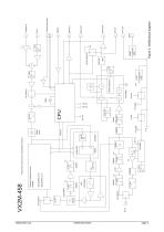
Figure 2: VX2M block diagram Radiometrix Ltd
Open the catalog to page 2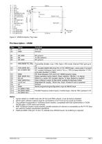
Input gain. Figure 3: VX2M Footprint (Top) view RF ground To the antenna RF ground Transmitter Enable. Low = ON, Open = RX mode. Internal 10k pull-up to 4V DC coupled digital data input for 3-12V CMOS logic. Leave open if unused AC coupled Analogue Input Limit to 1Vpk-pk 10% to keep distortion <1.5% and peak deviation >2.5kHz DC level between 0.5V and 2.5V. 60dB dynamic range Noise operated carrier detect. Open collector. ON/low = no signal 600mVpk-pk audio. DC coupled, approx 1V bias. Muted by squelch Open collector output of data slicer suitable for Biphase codes Regulated DC supply. 75mA...
Open the catalog to page 3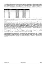
VX2M can be directly interfaced to a host microcontroller which can generally be powered by the regulated +4.4V output on pin 8 of VX2M. Three I/O pins on the microcontroller port can be assigned to select the first 8 channels on frequency table of the appropriate band for which the module is configured by pulling the P1P3 pins low. Channel select pins of VX2M have internal pull-up to 4V supply rail, hence channel selection operate on inverted logic. Channel 0 1 2 3 4 5 6 7 Digital Received Data Output (RXD) pin is an open collector output, which should be pulled-up to required voltage swing...
Open the catalog to page 4
Received Signal Strength 2.5 2.3 2.1 RF Level (dBm) Figure 4: RSSI voltage variation with respect to RF level at VX2M If the microcontroller has a built-in Analogue to Digital Converter (ADC), the Received Signal Strength Indicator (RSSI) output voltage level can be read by the microcontroller to estimate its distance from transmitting VX2M unit or identify areas of weak signal reception. RSSI can also be used to make a decision to switch to the second antenna in fixed installations within building where the probability of null-spots are higher. Regulatory Restrictions There is a generic 10%...
Open the catalog to page 5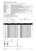
VX2M serial configuration commands 2400 baud RS232. 8 bit data, no parity, 1 start bit, 1 or 2 stop bits, No flow control SINGLE nnnnn Set value of N for single channel operation GOCHAN xx Serial select of channel xx (0 to 127) LOADMX xx Set highest permitted (serial selected) channel xx (others default to ch0) LOAD aa nnnnn Set value of N for channel aa (channels 0 to 15) LOADTB nnnnn Set value of N for channel 16 (channels 17 to 127 then in sequence) RVALUE rrrr Enter value for R register SETPAR Channel selected by 3 bit parallel input (0 to 7). Disable modem SETSER Channel selected by most...
Open the catalog to page 6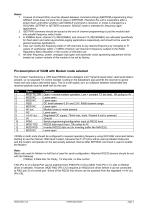
Notes: 1. A pause of at least 50ms must be allowed between command strings (EEPROM programming time) SINGLE mode does not store the N value in EEPROM. Therefore the unit is inoperative after a power down until either another valid SINGLE command is received, or mode is changed by a GOCHAN, SETPAR or SETSER command. SINGLE mode is intended for frequency agile applications. 2. /SETPAR command should be issued at the end of channel programming to put the module back into parallel frequency select mode 3. In 458MHz band, channel 12 (458.825MHz) and channel 15 (458.900MHz) are allocated specifically...
Open the catalog to page 7
Condensed specifications Frequency Frequency stability Channel spacing Number of channels 458.5-459.1MHz or 433-434MHz (any 3MHz band from 400-475MHz) +/- 1.5kHz 25kHz (12.5kHz by special order) 128 channels controlled via RS232 interface (8 parallel selected) voltage Current Operating temperature Size Spurious radiations Interface user Power RF Recommended PCB hole size -20 to +70 οC (Storage -30 to +70 οC) 59 x 38 x 10 mm Compliant with ETSI EN 300 220-3 and EN 301 489-3 Intended approval ETSI Radio standard EN 300 220-3 and EMC standard EN 301 489-3 Transmitter Output power TX on switching...
Open the catalog to page 8
Radiometrix Ltd Hartcran House 231 Kenton Lane Harrow, Middlesex HA3 8RP ENGLAND Tel: +44 (0) 20 8909 9595 Fax: +44 (0) 20 8909 2233 [email protected] www.radiometrix.com Copyright notice This product data sheet is the original work and copyrighted property of Radiometrix Ltd. Reproduction in whole or in part must give clear acknowledgement to the copyright owner. Limitation of liability The information furnished by Radiometrix Ltd is believed to be accurate and reliable. Radiometrix Ltd reserves the right to make changes or improvements in the design, specification or manufacture of its...
Open the catalog to page 9All Radiometrix catalogs and technical brochures
 LNM2H
LNM2H13 Pages
 NiM1B
NiM1B13 Pages
 WRX2C
WRX2C9 Pages
 MSR3
MSR38 Pages
 LMR0
LMR010 Pages
 SAT3
SAT35 Pages
 NTX2B
NTX2B13 Pages
 NTX0
NTX08 Pages
 MTX3
MTX310 Pages
 MTX2
MTX210 Pages
 BiM3H
BiM3H8 Pages
 QPX1
QPX18 Pages
 QPT1
QPT18 Pages
 AiM1
AiM19 Pages
 Universal Evaluation Kit
27 Pages
 TDL2A Evaluation Kit
4 Pages
 SPM2/RPM Evaluation Kit
7 Pages
 SP2 Evaluation Kit
12 Pages
 M48A Application Board
12 Pages
 M1144
M11448 Pages
 DXT / DXR
7 Pages
 Control44 Evaluation Kit
7 Pages
 CTA28 App. boards
11 Pages
 BL118
BL1187 Pages
 BD118
BD1185 Pages
 PAN1311
2 Pages
 PAN1310
2 Pages
 m48a
m48a11 Pages
 LMR2
LMR211 Pages
 TDL3F
TDL3F10 Pages
 krx2
krx29 Pages
 KTX2
KTX28 Pages
 RPM3
RPM315 Pages
 ENX1
ENX111 Pages
 NiM2
NiM211 Pages
 BiM1
BiM115 Pages
 RX3G
RX3G6 Pages
 PLR2
PLR212 Pages
 MSR3
MSR38 Pages
 CXR2
CXR212 Pages
 COR3
COR38 Pages
 TX2S
TX2S7 Pages
 CXT2
CXT212 Pages
 KRX2
KRX29 Pages
 KFX2
KFX24 Pages
 KDEC
KDEC5 Pages
 TXL2
TXL211 Pages
 Radiometrix
20 Pages


- Wireless remote control
- Industrial remote control
- Remote control with buttons
- Radio receiver
- On/off remote control
- Data transceiver
- Industrial receiver
- Bourn And Koch radio transceiver
- Industrial modem
- Serial receiver
- Multi-channel receiver
- Wireless receiver
- RS232 modem
- Data modem
- High-speed transceiver
- RS232 receiver
- Digital receiver
- Ethernet modem