
- Catalogs
- Radiometrix
- Universal Evaluation Kit

Universal Evaluation Kit

Universal Evaluation Kit
Catalog excerpts

This Evaluation Kit can be used to evaluate single frequency Radiometrix VHF/UHF transmitter, receiver and transceiver modules. LED indicators are provided to show system status and to facilitate range testing and site surveys. The board is controlled by the Eval-RPC chip and incorporates several useful diagnostics & debug modes. Link-selectable 9.6kbps or 64kbps data rate. Range of facilities include: • Range Testing • Target Environment T esting • Noise and Interference Identification • Antenna Evaluation Transient Analysis Communication Eye Diagram Universal Evaluation Board Analogue and digital data transmission TX1(H)/HX1/RX1, NTX2/NRX2, TX2(A)/TX2H/RX2(A), TX3A/RX3A, BiM1T/ BiM1R, CVR1, BiM/1/2/3A and NiM2 hardware test Received Signal Strength Indicator (RSSI) meter Linking external hardware directly or via on board Eval RPC Responses up to 9.6kbps (A) or 64 kbps (F) The Eval-RPC is based upon a modified RPC-000-DIL design and provides management of all the necessary data and control lines. The user can define both operational mode and data bit rate simply by selecting the required positions on the provided DEBUG switch and the various jumpers. Indication of unit status is provided by means of LEDs for Power, Transmit, Receive, Carrier Detect, Signal and OK (link success) functions. The Universal Evaluation Kit should include the following components and documentation: 2 Analogue input/output boards 2 Parallel port interface adaptor 2 1/4 wavelength whip for 433MHz, 869/914MHz and helical antennas for 173MHz 2 20.48MHz crystals for 160kbps operation (optional) In addition to the above a 2-channel (or even better, a 4-channel) digital storage oscilloscope is highly recommended as a means of monitoring system operation. Radiometrix Ltd Universal Evaluation Kit Page 1
Open the catalog to page 1
The following status LEDs will be activated depending on which mode is selected: Radiometrix Ltd Universal Evaluation Kit Page 2
Open the catalog to page 2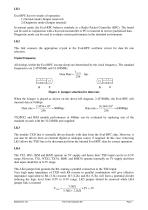
LK1 Eval RPC has two modes of operation: 1) Normal mode (Jumper removed) 2) Diagnostic mode (Jumper inserted) In normal mode, the Eval-RPC behaves similarly to a Radio Packet Controller (RPC). The board can be used in conjunction with a host microcontroller or PC to transmit & receive packetised data. Diagnostic mode can be used to evaluate system performance in the intended environment. LK2 This link connects the appropriate crystal to the Eval-RPC oscillator circuit for data bit rate selection. Crystal Frequency All timings within the Eval RPC (except sleep) are determined by the clock frequency....
Open the catalog to page 3
LK5 Removing the LK4 jumper and linking the LK5 returns the Eval-RPC drive amplitude of module TXD back to 0-5V LK6 The RX2 and BiM/BiM2 modules have Carrier Detect (CD) output instead of RSSI output featured on RX1, RX2A, NRX2, RX3A, BiM1 and BiM3A modules. Inserting the LK6 will enable the CD LED to work with RX2 and BiM/BiM2 modules. It should be removed when evaluating modules with RSSI output and CD LED output should also be ignored.
Open the catalog to page 4
Diagnostic Modes To enter the DEBUG mode, Jumper Link (LK1) (below the 9V battery) should be connected across TXR and 0V pin. The RESET button should be pressed while the Jumper Link is connected across TXR and 0V. Note: All the Oscilloscope screen capture and Spectrum Analyser screen capture given on the manual are instantaneous and they will vary with time. Mode 0 - Preamble Detector Applies to Evaluation Kit with Receiver: Insert Receiver module in one of the Evaluation Kit and Transmitter module on another. Transmitting and Receiving unit should operate at same data rate. i.e. LK2 position...
Open the catalog to page 5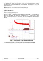
The AF output is at 1.16V DC with about 240mV AC sine wave, which is digitised by the Adaptive Data Slicer in the Receiver to re-produce the received preamble. (Ground level of AF is at the bottom of the screen) Note: LK3 should be removed when connecting analogue I/O board. Mode 1 - Pulsed Receiver Applies to Evaluation Kit with Receiver: Receiver is switched on for about 7ms and Eval RPC checks for preamble. If preamble is detected the SIGNAL line is pulled low. This will light up the SIGNAL LED. If not, the Receiver is turned off for about 10ms and the process is repeated. OK LED will also...
Open the catalog to page 6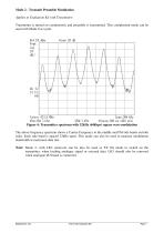
Mode 2 - Transmit Preamble Modulation Applies to Evaluation Kit with Transmitter: Transmitter is turned on continuously and preamble is transmitted. This complement mode can be used with Mode 0 as a pair. Figure 4: Transmitter spectrum with 32kHz (64kbps) square wave modulation The above frequency spectrum shows a Carrier Frequency in the middle and FM side bands on both sides. Each side band is spaced 32kHz apart. This mode can also be used to measure modulation bandwidth at maximum data rate. Note: Mode 2, with LK3 removed, can be also be used as TX On mode to switch on the transmitter, when...
Open the catalog to page 7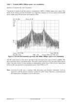
Mode 3 - Transmit 100Hz (200bps) square wave modulation Applies to Evaluation Kit with Transmitter Transmitter is turned on and the carrier is modulated by 100Hz or 200bps square wave signal. This mode can be used to test the Transmitter on a Spectrum Analyser. It can be used to measure RF power output, peak FM deviation and frequency offset. Figure 5: TX2-433-40 transmitter spectrum with 100Hz (200bps) square wave modulation The RF output power on the above spectrum is the maximum peak value of about +10dBm. The above spectrum shows 2 prominent peaks. The peak to peak spacing is twice the peak...
Open the catalog to page 8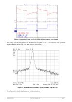
Figure 6: transmitted and received 100Hz (200bps) square wave signal RF Carrier will not be modulated by the data from Eval RPC if the LK3 is removed. The spectrum of unmodulated carrier with TXD held at 0V is given below. Figure 7: unmodulated transmitter spectrum when TXD is at 0V It can be used to check the phase noise of the transmitter.
Open the catalog to page 9
Mode 4 - Transmit Random Code Applies to Evaluation Kit with Transmitter: Transmitter is turned on and the carrier is modulated by a 8 bit maximal length (255) pseudorandom code at 15.6µs per bit (at 64kbps). On the receiving end, the data output AF line can be connected to an Oscilloscope to obtain an eye diagram. Figure 8: transmitted and received pseudo-random code Eye Diagram An eye diagram is an oscilloscope display in which a pseudo-random analogue data signal from AF output of a receiver is repetitively sampled and applied to the vertical input, while the data rate (RXR) on the transmitting...
Open the catalog to page 10All Radiometrix catalogs and technical brochures
 LNM2H
LNM2H13 Pages
 NiM1B
NiM1B13 Pages
 VX2M
VX2M9 Pages
 WRX2C
WRX2C9 Pages
 MSR3
MSR38 Pages
 LMR0
LMR010 Pages
 SAT3
SAT35 Pages
 NTX2B
NTX2B13 Pages
 NTX0
NTX08 Pages
 MTX3
MTX310 Pages
 MTX2
MTX210 Pages
 BiM3H
BiM3H8 Pages
 QPX1
QPX18 Pages
 QPT1
QPT18 Pages
 AiM1
AiM19 Pages
 TDL2A Evaluation Kit
4 Pages
 SPM2/RPM Evaluation Kit
7 Pages
 SP2 Evaluation Kit
12 Pages
 M48A Application Board
12 Pages
 M1144
M11448 Pages
 DXT / DXR
7 Pages
 Control44 Evaluation Kit
7 Pages
 CTA28 App. boards
11 Pages
 BL118
BL1187 Pages
 BD118
BD1185 Pages
 PAN1311
2 Pages
 PAN1310
2 Pages
 m48a
m48a11 Pages
 LMR2
LMR211 Pages
 TDL3F
TDL3F10 Pages
 krx2
krx29 Pages
 KTX2
KTX28 Pages
 RPM3
RPM315 Pages
 ENX1
ENX111 Pages
 NiM2
NiM211 Pages
 BiM1
BiM115 Pages
 RX3G
RX3G6 Pages
 PLR2
PLR212 Pages
 MSR3
MSR38 Pages
 CXR2
CXR212 Pages
 COR3
COR38 Pages
 TX2S
TX2S7 Pages
 CXT2
CXT212 Pages
 KRX2
KRX29 Pages
 KFX2
KFX24 Pages
 KDEC
KDEC5 Pages
 TXL2
TXL211 Pages
 Radiometrix
20 Pages


- Wireless remote control
- Industrial remote control
- Remote control with buttons
- Radio receiver
- On/off remote control
- Data transceiver
- Industrial receiver
- Radio transceiver module
- Serial receiver
- Industrial modem
- Multi-channel receiver
- Wireless receiver
- RS232 modem
- High-speed transceiver
- Data modem
- RS232 receiver
- Digital receiver
- Ethernet modem