
- Catalogs
- Radiometrix
- TDL3F

TDL3F

TDL3F
Catalog excerpts
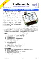
Transparent Data Link on 868/914MHz band A TDL3F is a single channel, 869 or 915MHz wideband, transparent data link. It has a TDL2A pin out (and , but uses a BiM3 series radio module. TLD3F acts as a transparent serial cable to attached host. TDL3F is a n intermediate level OEM radio modem which is in between a raw FM radio module like BiM3B and a sophisticated OEM radio modem like R PM3. It takes care of preamble, synchronisation, bit balancing and error checking along with automatic n oise squelching. Figure 1: TDL3F-868.30-9 radio modem The TDL3F provides a half duplex link. Provided no two devices attempt to transmit simultaneously no further restrictions on data transmission need be made, as all transmit timing, valid data identification and datastream buffering is conducted by the unit. Synchronisation and framing words in the packet prevent the receiver outputting garbage in the absence of wanted RF signal or presence of interference. For multiple radio systems (polled networks) a TDL3F can be set to 1 of 8 unique addresses. Features • Conforms to EN 300 220-3 and EN 301 489-3 • Crystal controlled PLL FM circuitry for both Tx and Rx • SAW front-end filter • Single conversion superhet • Serial modem baud rate at 9600bps (half-duplex) • Addressable point-to-point Applications • PDAs, organisers & laptops • Handheld / portable terminals • EPOS equipment, barcode scanners • In-building environmental monitoring and control • Remote data acquisition system, data logging • Fleet management, vehicle data acquisition Technical Summary • Operating frequency: 869.85 / 868.30MHz (Europe), 914.5MHz (North America) • Modulation: 16kbps bi-phase FSK • Supply: 5V at 18mA transmit (@5mW), 15mA receive/idle • Transmit power: +5mW @ 869.85MHz) • Receiver sensitivity: -106dBm (for 1% BER) • 32 byte data buffer
Open the catalog to page 1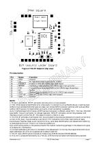
1. Pinout is as TDL2A. On RF connector end only pins 1,2,3 are present. 2. TXD / RXD are inverted RS232 at 5v cmos levels. To connect to a true RS232 device, inverting level shifters must be used (MAX232 type are ideal, but simple NPN transistor switches with pullups often suffice). With typical microcontrollers and uarts, direct connection is possible. 2a An interface board which takes a BiM3 series transceiver is offered, called TDi3 . This has MAX232 type buffer, 9 way D connector, 5v voltage regulator, SMA RF connector and all the processor and interface circuitry of the TDL3F. This board...
Open the catalog to page 2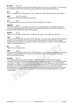
RF Ground pin, internally connected to the module screen and pin 8, 9, 10 and 18 (0 V). This pin should be connected to the RF return path (e.g. co-axial cable braid, main PCB ground plane, etc). RF pin 2 50Q RF input/output from the antenna, it is DC isolated internally. (see antenna section for details). GND pin 8, 9, 10 and 18 Supply ground connection to ground plane and can. VCC pin 17 5V voltage regulator should be used to have a clean 5V supply to the module Active low Enable pin. It has a 10kQ pull-ups to Vcc. It should be pulled Low to enable the module. This can also...
Open the catalog to page 3
Serial interface – modem operation To connect to a true RS232 device, inverting RS232-CMOS level shifters must be used. Maxim MAX232 or equivalent are ideal, but simple NPN transistor switches with pull-ups often suffice. With typical microcontrollers and UARTs, direct connection is possible. The Radio / data stream interface A 32 byte software FIFO is implemented in both the transmit and receive sub-routine. At the transmitting end this is used to allow for the transmitter start up time (about 4mS), while on receiving end it buffers arriving packets to the constant output data rate. All timing...
Open the catalog to page 4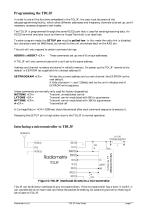
In order to use all the functions embedded in the TDL3F, the user must be aware of the setup/programming facility, which allow different addresses and frequency channels to be set up, and if necessary accesses diagnostic test modes. The TDL3F is programmed through the same RS232 port that is used for sending/receiving data. An RS232 terminal emulator (such as Aterm or HyperTerminal) is an ideal tool. To enter program mode, the SETUP pin must be pulled low. In this mode the radio link is disabled, but characters sent (at 9600 baud, as normal) to the unit are echoed back on the RXD pin. The unit...
Open the catalog to page 5
Serial data should be in the following format: 1 start bit, 8 data bits, no parity, 1 or 2 stop bits 9600bps 0V=low, 5V=high STATUS pin can be connected to one of the port pins which can generate an interrupt on low-to-high transition (e.g. RB0/INT pin in the PIC). This can be used to enter a receive sub-routine to download data received from remote TDL3F. Therefore, the host does not need to wait in a loop for a packet. Range test and site survey can be carried out by connecting an LED on the STATUS pin. Every time, TDL3F is within range to receive valid data, the LED will flicker. Figure 6:...
Open the catalog to page 6
Condensed specifications
Open the catalog to page 7
Antenna considerations and options The choice and positioning of transmitter and receiver antennas is of the utmost importance and is the single most significant factor in determining system range. The following notes are intended to assist the user in choosing the most effective arrangement for a given application. Nearby conducting objects such as a PCB or battery can cause detuning or screening of the antenna which severely reduces efficiency. Ideally the antenna should stick out from the top of the product and be entirely in the clear, however this is often not desirable for practical or...
Open the catalog to page 8
Note: Where the specified antennas are mounted on the PCB and/or in close proximity to metalwork (module casing, components, PCB tracking etc), the antenna radiation pattern may be seriously affected. Radiated power may be significantly increased in some directions (sometimes by as much as 10dB) and correspondingly reduced in others. This may adversely affect system performance where good all-round coverage is desired. Care should also be taken to ensure that this effect does not increase the radiated power in any direction beyond that allowed by type approval regulations. Where this occurs the...
Open the catalog to page 9All Radiometrix catalogs and technical brochures
 LNM2H
LNM2H13 Pages
 NiM1B
NiM1B13 Pages
 VX2M
VX2M9 Pages
 WRX2C
WRX2C9 Pages
 MSR3
MSR38 Pages
 LMR0
LMR010 Pages
 SAT3
SAT35 Pages
 NTX2B
NTX2B13 Pages
 NTX0
NTX08 Pages
 MTX3
MTX310 Pages
 MTX2
MTX210 Pages
 BiM3H
BiM3H8 Pages
 QPX1
QPX18 Pages
 QPT1
QPT18 Pages
 AiM1
AiM19 Pages
 Universal Evaluation Kit
27 Pages
 TDL2A Evaluation Kit
4 Pages
 SPM2/RPM Evaluation Kit
7 Pages
 SP2 Evaluation Kit
12 Pages
 M48A Application Board
12 Pages
 M1144
M11448 Pages
 DXT / DXR
7 Pages
 Control44 Evaluation Kit
7 Pages
 CTA28 App. boards
11 Pages
 BL118
BL1187 Pages
 BD118
BD1185 Pages
 PAN1311
2 Pages
 PAN1310
2 Pages
 m48a
m48a11 Pages
 LMR2
LMR211 Pages
 krx2
krx29 Pages
 KTX2
KTX28 Pages
 RPM3
RPM315 Pages
 ENX1
ENX111 Pages
 NiM2
NiM211 Pages
 BiM1
BiM115 Pages
 RX3G
RX3G6 Pages
 PLR2
PLR212 Pages
 MSR3
MSR38 Pages
 CXR2
CXR212 Pages
 COR3
COR38 Pages
 TX2S
TX2S7 Pages
 CXT2
CXT212 Pages
 KRX2
KRX29 Pages
 KFX2
KFX24 Pages
 KDEC
KDEC5 Pages
 TXL2
TXL211 Pages
 Radiometrix
20 Pages


- Wireless remote control
- Industrial remote control
- Remote control with buttons
- Radio receiver
- On/off remote control
- Data transceiver
- Industrial receiver
- Radio transceiver module
- Serial receiver
- Industrial modem
- Multi-channel receiver
- Wireless receiver
- RS232 modem
- High-speed transceiver
- Data modem
- RS232 receiver
- Digital receiver
- Ethernet modem