
Catalog excerpts
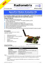
SpacePort Modem Evaluation KitSupports Point to Multi Point and Broadcast Mode Test The SpacePort Modem Evaluation Kit enables SPM / RPM to be transformed into a complete Radio Modem with DCE type RS232 interface. Range of Features ♦ Direct interface to RS232 serial port ♦ Onboard regulator can provide 5V, 1A supply to power-up DTE (e.g. barcode scanner) ♦ Visual indications of operation through LEDs ♦ Access to internal diagnostic/Test modes using HyperTerminal ♦ Access to each data/control pins for external interface or testing ♦ Set-up and configuration using HyperTerminal ♦ Built-in command line configuration. ♦ PP3 9V battery powered. DC jack and terminal block provided for external supply Kit Contents The SPM Evaluation Kit comes with the following contentes: 2 SPM Evaluation Board1 2 SPM/RPM modules (ordered separately) 2 2 1/4 wavelength whip antenna 1 SPM data sheet 1 SPM Eval-Kit data sheet Figure 1: SpacePort Modem Evaluation Kit Visual Facilities The following status LEDs will be activated depending on the SPM operation mode. Notes: 1. The standard SPM evaluation kit comes with 2 Evaluation Board. In order to test the point to multipoint and broadcast modes of the SPM, at least 3 Evaluation Board would be required. 2. BNC connector can be replaced with SMB connector or terminal block to use different antenna connection Radiometrix Ltd, SPM Eval-Kit page 1
Open the catalog to page 1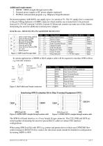
1. DB9M - DB9F straight through serial cable 2. External power supply or DC power adaptor (optional) 3. PC/PDA with terminal program (e.g. Hilgraeve HyperTerminal) On-board regulator (LM340TS) can supply up to 1A current at 5V. The 5 V supply line is connected to the pin 9 (Ring Indicator) of DB9F connector which enables any external host to be powered from pin 9 (+5V DC) and pin 5 (GND). Certain CCD barcode scanner can make use of this feature, eliminating the need for additional external power adaptor. Serial Pin outs - RS232 (EIA/TIA-574) and RS232D (EIA/TIA-561) In certain applications...
Open the catalog to page 2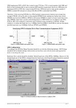
SPM implements DTE to DCE flow control using CTS line. CTS is wired together with DSR and DCD in the Evaluation Kit to meet common DTE interface requirement. However, SPM does not implement DCE to DTE flow control using RTS line. DTR line used to wake up the module if SHDN is turned ON and put it to sleep if the Host (DTE) is detached from SPM. Therefore, if the receiving DTE(B) [e.g. EPoS printer] cannot process [print] received data fast enough, DTE(B) will not be able to stop attached SPM(B) from sending any further data which SPM(B) received from SPM(A). SPM(A) will assume SPM(B) is...
Open the catalog to page 3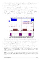
SPM has a 2mm pitch pin-out for embedded system applications where PCB space is very limited. However, for the convenience of evaluating the module, separate rows of 0.1” pitch pin headers are provided on both sides of the SPM sockets. Oscilloscope probes can be easily connected on these to monitor data transmission on each stage from serial RS232 type data entering SPM, FRPC transmitting packetised data, SPM on receiving end sending serial data to attached Host and sending back Packet Acknowledgements. Oscilloscope screen capture below were taken during a large file transfer at 115,200bps...
Open the catalog to page 4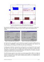
Figure 10: Serial RS232 data transmission with packet acknowledgement By turning the ACKMODE OFF, the overall data throughput can be increased up to 55kbps with SPM2-433-28. In this fast mode, SPM(A) will not wait for a packet acknowledgement from SPM(B). Figure 11: File transfer with ACKMODE ON Figure 12: File transfer with ACKMODE OFF In broadcast mode, same data/file can be transferred to several hosts attached to SPM Eval Kits at the same time. ACKMODE is should also be turned OFF in broadcast mode otherwise the acknowledgements from multiple slave SPMs will cause master SPM hang up....
Open the catalog to page 5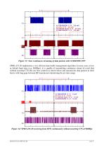
Figure 13: Near continuous streaming of data packets with ACKMODE OFF SPM2-433-28 implements a very efficient data buffer management algorithm. In most cases at low or default baud rates (e.g. 9600bps), it is capable of transmitting continuous stream of serial data without asserting CTS line (no flow control) as shown below and transmit the data packets in short bursts with long gaps between RF transmission minimising the air-time usage. Figure 14: SPM2-433-28 receiving from DTE continuously without asserting CTS at 9600bps
Open the catalog to page 6
Copyright notice This product data sheet is the original work and copyrighted property of Radiometrix Ltd. Reproduction in whole or in part must give clear acknowledgement to the copyright owner. Limitation of liability The information furnished by Radiometrix Ltd is believed to be accurate and reliable. Radiometrix Ltd reserves the right to make changes or improvements in the design, specification or manufacture of its subassembly products without notice. Radiometrix Ltd does not assume any liability arising from the application or use of any product or circuit described herein, nor for...
Open the catalog to page 7All Radiometrix catalogs and technical brochures
-
LNM2H
13 Pages
-
NiM1B
13 Pages
-
VX2M
9 Pages
-
WRX2C
9 Pages
-
MSR3
8 Pages
-
LMR0
10 Pages
-
SAT3
5 Pages
-
NTX2B
13 Pages
-
NTX0
8 Pages
-
MTX3
10 Pages
-
MTX2
10 Pages
-
BiM3H
8 Pages
-
QPX1
8 Pages
-
QPT1
8 Pages
-
AiM1
9 Pages
-
Universal Evaluation Kit
27 Pages
-
TDL2A Evaluation Kit
4 Pages
-
SP2 Evaluation Kit
12 Pages
-
M48A Application Board
12 Pages
-
M1144
8 Pages
-
DXT / DXR
7 Pages
-
Control44 Evaluation Kit
7 Pages
-
CTA28 App. boards
11 Pages
-
BL118
7 Pages
-
BD118
5 Pages
-
PAN1311
2 Pages
-
PAN1310
2 Pages
-
m48a
11 Pages
-
LMR2
11 Pages
-
TDL3F
10 Pages
-
krx2
9 Pages
-
KTX2
8 Pages
-
RPM3
15 Pages
-
ENX1
11 Pages
-
NiM2
11 Pages
-
BiM1
15 Pages
-
RX3G
6 Pages
-
PLR2
12 Pages
-
MSR3
8 Pages
-
CXR2
12 Pages
-
COR3
8 Pages
-
TX2S
7 Pages
-
CXT2
12 Pages
-
KRX2
9 Pages
-
KFX2
4 Pages
-
KDEC
5 Pages
-
TXL2
11 Pages
-
Radiometrix
20 Pages


