- Catalogs
- Radiometrix
- SP2 Evaluation Kit
SP2 Evaluation Kit
1 /12Pages

SP2 Evaluation Kit
1 /12Pages
Catalog excerpts

SpacePort Evaluation Kit SpacePort Evaluation Kit can be used to evaluate the Radiometrix SpacePort, Radio Packet Controller modules. LED indicators are provided to show system status and to facilitate range testing and installation site surveys. Internal EEPROM values can be configured through parallel port connection to PC using RPC Development Kit Software. Features • A pair of Evaluation PCBs to evaluate SP2, RPC and FRPC modules • Direct interface to Parallel port • Visual indications of operational mode and test results through LEDs • Access to internal diagnostic/Test modes and EEPROM using RPC Development Kit Software • All I/O are brought out with adjacent headers for developing applications and analyzing signals • PP3 9V Battery operation makes the board portable for easy wireless evaluation Kit contents • 2 SP2-433-160 modules (RPC or FRPC should be ordered separately) • 2 1/4 wavelength whip antennas (433MHz) Optional requirement • DB25M-DB25F parallel extension/straight through cable • PC/laptop with ECP parallel port with MS-DOS, Win3.X, Win95/98. • RPC Development Kit Software The following status LEDs will be activated depending on which mode is selected: Radiometrix Ltd SpacePort Evaluation Kit Manual page 1
Open the catalog to page 1
1. Standalone Operation This mode selects the internal diagnostics modes built into the RPC, FRPC or SP2. Set-up • Connect the 1/4 wavelength antenna into the antenna terminal on the evaluation board. Plug the SP2 into the DIL socket marked SpacePort. RPC/FRPC should be plugged in with RPC/FRPC IC facing the Evaluation Kit and shielding can or module facing the other way. • Connect a 7.5VDC-24VDC supply or 9V battery to the supply input terminals and slide the power switch to ON position. • Put the DEBUG jumper on and press 'Reset' • The Hex switch selects the required debug mode 0 to 8. A reset...
Open the catalog to page 2
Mode 4 - Transmit Random Code Transmitter is turned on and the carrier is modulated by a 8 bit maximal length (255) pseudo-random code at 6.25µs per bit (at 160kbps). On the receiving end, the data output AF line can be connected to an Oscilloscope to obtain an eye diagram. An eye diagram is an oscilloscope display in which a pseudo-random data signal from AF output of a receiver is repetitively sampled and applied to the vertical input, while the data rate (RXR) on the transmitting unit is used to trigger the horizontal sweep. System performance information can be derived by analyzing the display....
Open the catalog to page 3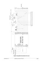
Voltage regulator Radiometrix Ltd SpacePort Evaluation Kit Manual page 4
Open the catalog to page 4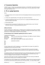
If RESET jumper is inserted, the internal Packet Controller IC will be RESET leaving direct access to raw RF Transceiver. Jumper across RX-GND will enable receiver circuit and jumper across TX-GND will enable transmitter circuit. 3. PC or Laptop Operation Set-up • Connect the antenna into the antenna terminal on the development board and also plug the SP2 into the socket. • Connect a DC supply/9V battery to the supply input terminals and switch on. • Connect the development board to the LPT port of a PC or Laptop with DB25M-DB25F parallel extension/straight through cable • Remove debug jumper. •...
Open the catalog to page 5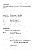
hiding or showing the user memory area. In order to view the help list properly the display needs to be in the expanded mode. Messages sent from the SP2 are displayed under the Outgoing (TX) message heading to the left of the display. Messages received by the SP2 are displayed under the Incoming (RX) heading to the right of the display. Command set: The following list has been taken from the RPC demonstration program and details the commands which are available for evaluating the SP2. COMMAND Reset [n] reaD address Send [$] string Write address data Clear switcH or <TAB> File [delay] file [file...] Test stoP...
Open the catalog to page 6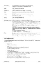
eXit or <F3> Clear stoP or <AX> Help <TAB> <ESC> Typing either EXIT or X, or pressing F3 will exit from the demonstration program back to the command prompt. Clear the display output window. Stop the repeating file send (Test & File commands). Display this help information as shown in section SP2DEMO commands. Switches the display between the memory display and the expanded output display. Clear the current command line File [delay] file [file...] Send a file to the SP2. A maximum of 3 files can be given on the command line. The file names should contain only alpha characters (e.g. fred1.txt...
Open the catalog to page 7
Appendix A Using a printer port to drive the SP2. For New PCs: Bi-directional Port (PS/2) Port requirement 8 bit bi-directional PS/2 (PS/2 or ECP set to PS/2 Mode / Byte Mode) In PS/2 Mode, Status Lines are used for Control line input from SP2 (RXR, TXA) and Printer Port Control Lines are used to output the SP2 Control signals (RXA & TXR). In Bidirectional PS/2 mode, Printer port data lines can be used as SP2 data lines in bidirectional mode. Most of the PCs come with Extended Capabilities Port (ECP). ECP can be set to operate in PS/2 compatible bidirectional mode. Program supplied with bidirectional...
Open the catalog to page 8
SP2 Evaluation Kit can be interfaced to a Host PIC microcontroller as shown above. PIC16F870 has PortB with 8 I/O pins which can be assigned to communicate with SP2 Eval Kit. UART in PortC can be interfaced to a Serial COM Port via an RS232 driver. The following subroutines may by used by a PIC16F870 host microcontroller to upload serial data it received from its serial port to SP2 and download the data packet from SP2 and send it out via its serial port to a PC. OUT_BYTE & IN_BYTE Additionally LISTEN_BUS is called on completion of a packet transfer to the SP2 to return the data bus to high impedance...
Open the catalog to page 9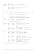
ONRESET GOTO START ; jump to main program ; Initialise PORT B to drive SP2. select Bank 1 TXR & RXA O/P, Rest as inputs select bank 0 SUBROUTINE - IN_BYTE IN_BYTE - READ A BYTE FROM THE SP2 INTO FILE (REGISTER) POINTED TO BY FSR W IS DESTROYED NOTE - THIS ROUTINE WILL HANG THE HOST UNTIL THE HOST COMPLETES THE TRANSFER OF TWO NIBBLES - THIS SUBROUTINE CAN BE CONFIGURED TO RUN AS PART OF AN INTERUPT HANDLER IF THE RXR LINE FROM THE SP2 IS USED TO TRIGGER A HOST INTERUPT IN_BYTE BTFSC SP2,RXR ; WE GOT A RX REQUEST YET ? GOTO IN_BYTE ; NO , SO LOOP BACK AND WAIT READ THE LS NIBBLE...
Open the catalog to page 10All Radiometrix catalogs and technical brochures
 LNM2H
LNM2H13 Pages
 NiM1B
NiM1B13 Pages
 VX2M
VX2M9 Pages
 WRX2C
WRX2C9 Pages
 MSR3
MSR38 Pages
 LMR0
LMR010 Pages
 SAT3
SAT35 Pages
 NTX2B
NTX2B13 Pages
 NTX0
NTX08 Pages
 MTX3
MTX310 Pages
 MTX2
MTX210 Pages
 BiM3H
BiM3H8 Pages
 QPX1
QPX18 Pages
 QPT1
QPT18 Pages
 AiM1
AiM19 Pages
 Universal Evaluation Kit
27 Pages
 TDL2A Evaluation Kit
4 Pages
 SPM2/RPM Evaluation Kit
7 Pages
 M48A Application Board
12 Pages
 M1144
M11448 Pages
 DXT / DXR
7 Pages
 Control44 Evaluation Kit
7 Pages
 CTA28 App. boards
11 Pages
 BL118
BL1187 Pages
 BD118
BD1185 Pages
 PAN1311
2 Pages
 PAN1310
2 Pages
 m48a
m48a11 Pages
 LMR2
LMR211 Pages
 TDL3F
TDL3F10 Pages
 krx2
krx29 Pages
 KTX2
KTX28 Pages
 RPM3
RPM315 Pages
 ENX1
ENX111 Pages
 NiM2
NiM211 Pages
 BiM1
BiM115 Pages
 RX3G
RX3G6 Pages
 PLR2
PLR212 Pages
 MSR3
MSR38 Pages
 CXR2
CXR212 Pages
 COR3
COR38 Pages
 TX2S
TX2S7 Pages
 CXT2
CXT212 Pages
 KRX2
KRX29 Pages
 KFX2
KFX24 Pages
 KDEC
KDEC5 Pages
 TXL2
TXL211 Pages
 Radiometrix
20 Pages


- Wireless remote control
- Industrial remote control
- Remote control with buttons
- Radio receiver
- On/off remote control
- Data transceiver
- Industrial receiver
- Bourn And Koch radio transceiver
- Industrial modem
- Serial receiver
- Multi-channel receiver
- Wireless receiver
- RS232 modem
- Data modem
- High-speed transceiver
- RS232 receiver
- Digital receiver
- Ethernet modem