 Website:
Radiometrix
Catalog excerpts

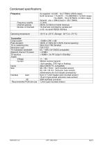
The QPT1 transmitter module offers a 2 watt RF output VHF radio link, in either a robust aluminium extruded casing, or a smaller footprint PCB mounted shield can. This unit is ideally suited to applcations where existing lower powered transmitters provide insufficient range. The QPT1 transmitter is a m ulti-channel, narrowband design, suitable for licensed and unlicensed VHF allocations, FCC part 90 operation, and the 2M amateur band. Together with a matching LMR1 or R X1M receiver a one-way radio data link can be achieved over a distance of well over 10km (with a suitable antenna)." Features Compliant with FCC part 90 PLL synthesizer with TCXO Data rates up to 5 kbps for standard module Usable range over 10km Re-programmable via RS232 interface Applications ■ Amateur radio ■ MURS units ■ Industrial telemetry and telecommand ■ High-end security systems ■ APRS systems ■ Vehicle data up/download ■ ROV/machinery controls Technical Summary ■ Operating frequency: 144.000 - 144.775 (25KHz steps) ■ Any 2MHz segment in 135 - 175MHz ■ 16 channels selected by parallel interface ■ or 32 channels by serial command ■ Transmit power: 2 W (+33dBm) nominal (1 watt version available) ■ Supply range: 12V (11 - 15V) ■ Current consumption: 550mA typ. ■ Data bit rate: 5kbps max ■ Size: 68 x 55 x 15mm (pcb mounted version) ■ 83 x 64 x 30 mm (extrusion case version) ■ (dimensions do not include connectors) Radiometrix Ltd QPT1 Data Sheet&nb
Open the catalog to page 1
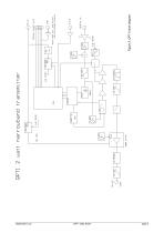
Figure 2: QPT1 block diagram Radiometrix Ltd
Open the catalog to page 2
Pin description (PCB mounted version) 1. No 'modem version' is available, but the PL_ and CX series firmware can be used 2. Parallel port has a 50K pullups to internal 4v rail 3. Caution. The TXD and P0-P3 inputs are not high voltage tolerant. Low voltage logic, or switches to ground, are required. 4. Overall thermal power dissipation in normal use is around 4 watts, rising to 6-7 watts under aerial fault conditions. 5. This is a 2 watt output product. Good grounding , good quality aerials, properly mounted, and a low impedence power supply are required if full performance is to be...
Open the catalog to page 3
1. No 'modem version' is available, but the PL_ and CX series firmware can be used 2. Parallel port has a 50K pullups to internal 4v rail, and 5v transorbs to ground 3. Caution. The TXD and P0-P3 inputs are not high voltage tolerant. Low voltage logic, or switches to ground, are required. 4. A simple RS232 voltage tolerant transistor inverter connects pin 14 to P0/PGM 5. Overall thermal power dissipation in normal use is around 4 watts, rising to 6-7 watts under aerial fault conditions. 6. This is a 2 watt output product. Good grounding , good quality aerials, properly mounted, and a low...
Open the catalog to page 4
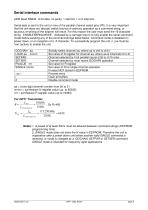
aa = a two digit channel number from 00 to 31 nnnnn = synthesizer N register value (up to 65535) rrrr = synthesizer R register value (up to 16383) Notes: 1. A pause of at least 50ms must be allowed between command strings (EEPROM programming time). 2. SINGLE mode does not store the N value in EEPROM. Therefore the unit is inoperative after a power down until either another valid SINGLE command is received, or mode is changed by a GOCHAN, SETPAR or SETSER command. SINGLE mode is intended for frequency agile applications. Radiometrix Ltd QPT1 Data Sheet page 5
Open the catalog to page 5
Radiometrix Ltd QPT1 Data Sheet page 6
Open the catalog to page 6
Data sheet links: http://www. radiometrix. co. uk/dsheets/qpt 1 .pdf http://www. radiometrix. co. uk/dsheets/imt 1lmr1.pdf Radiometrix Ltd QPT1 Data Sheet page 7
Open the catalog to page 7
Copyright notice This product data sheet is the original work and copyrighted property of Radiometrix Ltd. Reproduction in whole or in part must give clear acknowledgement to the copyright owner. Limitation of liability The information furnished by Radiometrix Ltd is believed to be accurate and reliable. Radiometrix Ltd reserves the right to make changes or improvements in the design, specification or manufacture of its subassembly products without notice. Radiometrix Ltd does not assume any liability arising from the application or use of any product or circuit described herein, nor for...
Open the catalog to page 8All Radiometrix catalogs and technical brochures
-
LNM2H
13 Pages
-
NiM1B
13 Pages
-
VX2M
9 Pages
-
WRX2C
9 Pages
-
MSR3
8 Pages
-
LMR0
10 Pages
-
SAT3
5 Pages
-
NTX2B
13 Pages
-
NTX0
8 Pages
-
MTX3
10 Pages
-
MTX2
10 Pages
-
BiM3H
8 Pages
-
QPX1
8 Pages
-
AiM1
9 Pages
-
Universal Evaluation Kit
27 Pages
-
TDL2A Evaluation Kit
4 Pages
-
SPM2/RPM Evaluation Kit
7 Pages
-
SP2 Evaluation Kit
12 Pages
-
M48A Application Board
12 Pages
-
M1144
8 Pages
-
DXT / DXR
7 Pages
-
Control44 Evaluation Kit
7 Pages
-
CTA28 App. boards
11 Pages
-
BL118
7 Pages
-
BD118
5 Pages
-
PAN1311
2 Pages
-
PAN1310
2 Pages
-
m48a
11 Pages
-
LMR2
11 Pages
-
TDL3F
10 Pages
-
krx2
9 Pages
-
KTX2
8 Pages
-
RPM3
15 Pages
-
ENX1
11 Pages
-
NiM2
11 Pages
-
BiM1
15 Pages
-
RX3G
6 Pages
-
PLR2
12 Pages
-
MSR3
8 Pages
-
CXR2
12 Pages
-
COR3
8 Pages
-
TX2S
7 Pages
-
CXT2
12 Pages
-
KRX2
9 Pages
-
KFX2
4 Pages
-
KDEC
5 Pages
-
TXL2
11 Pages
-
Radiometrix
20 Pages


