- Catalogs
- Radiometrix
- NiM1B
NiM1B
1 /13Pages

NiM1B
1 /13Pages
Catalog excerpts

Frequency Programmable 25kHz NBFM VHF Transceiver The narrow band NiM1B transceiver offers a low power, reliable data link in a Radiometrix transceiver standard pin out and footprint. The NiM1B is a frequency programmable, narrowband design, suitable for licensed and unlicensed VHF allocations, FCC part 90 and part 95 (MURS) operations. Conforms to EN 300 220-3 and EN 301 489-3 (10mW version only) Compliant with FCC part 90 and part 95 (MURS) Standard frequency 154.570MHz or 154.600MHz (re-programmable) Other frequencies from 120MHz to 175MHz Data rates up to 5kbps for standard module Usable range over 1km Fully screened Low power requirements 25kHz Channel spacing Feature-rich interface (true analogue and/or digital baseband) The NiM1B is a half duplex radio transceiver module for use in long range bi-directional data transfer applications at ranges up to 1kilometres. The module operates on the US 154MHz MURS band allocation. NiM1B is also available as separate NiM1BT transmitter and NiM1BR receiver, which can be, used as dualin-line equivalents of TX1 transmitter and RX1/NRX1 receiver respectively. Applications Multi-Use Radio Service (MURS) Industrial telemetry and telecommand High-end security systems Vehicle data up/download ROV/machinery controls Fully integrated sigma-delta PLL synthesizer based design High stability TCXO reference Data bit rate: 5kbps max. Transmit power: +13dBm (20mW) Image rejection: >70dB Receiver sensitivity: -120dBm (for 12dB SINAD) RSSI output with >50dBm range Supply: 3.3V - 15V @ 30mA transmit, 18mA receive Dimensions: 33 x 23 x 11mm (fully screened)
Open the catalog to page 1
Figure 2: NiM1B schematics Radiometrix Ltd., NiM1B transceiver data sheet
Open the catalog to page 2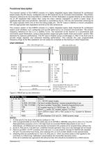
Functional description The transmit section of the NiM1B consists of a highly integrated sigma delta (fractional N) synthesizer based single chip RF device, configured over an SPI serial bus by an on-board microcontroller. The primary frequency reference for the transmitter is a 30MHz VC-TCXO. Modulation is applied directly to this reference via an AF baseband filter (rather than using the chip's internal modulator) to permit a wider range of baseband data rates and waveforms. Operation is controlled by the N_TXE line, the transmitter achieving full RF output typically within 5ms of this line...
Open the catalog to page 3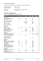
Absolute maximum ratings Exceeding the values given below may cause permanent damage to the module. Operating temperature Storage temperature Performance specifications: (Vcc = 5V / temperature = 20C unless stated) General DC supply Supply voltage TX Supply current (20mW) RX Supply current Antenna pin impedance RF centre frequency Channel spacing Number of channels Transmitter RF RF power output Spurious emissions Adjacent channel TX power Frequency accuracy FM deviation (peak) Baseband Modulation bandwidth @ -3dB TXD input level (logic low) TXD input level (logic high) Baseband Baseband bandwidth...
Open the catalog to page 4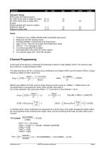
Dynamic timing RX enable with signal present N_RXE active (low) to stable AF output N_RXD active (low) to stable RXD output Signal applied with receiver enabled Signal to valid AF Signal to stable data Programs to any 154MHz MURS 25kHz bandwidth frequencies Measured into 50 resistive loads. Exceeds EN/EMC requirements at all frequencies. 5ppm TCXO. Total over full supply and temperature range. With 0V – 3.0V modulation input. To achieve specified FM deviation. See applications information for further details. For received signal with 3kHz FM deviation. Channel Programming At the heart of the...
Open the catalog to page 5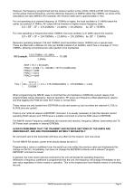
However, the frequency programmed into the receiver section is the LOCAL OSCILLATOR (LO) frequency, not the actual channel frequency, and the reference frequency is 26MHz rather than 30MHz, so some of the calculations are also different (For example, the minimum step size is approximately 4.1Hz) For unit operating on a channel frequency of 163MHz or higher, the local oscillator is 21.4MHz below the carrier (so subtract 21.4MHz). AF output will be inverted on higher receive frequency units. For units operating on frequencies below 156MHz, the local oscillator is 21.4MHz above the channel. Receivers...
Open the catalog to page 6
Serial interface commands NiM1B is programmable (in the same way as an NTX2B or NRX2B, or a NiM2B) using the N_Rxe or N_Txe pins. Reprogramming requires a 0v to +Vin logic level non-inverted RS232 data-stream to pin 3 (RX PGM) or 4 (TX PGM). An RS232 port can be directly connected to the enable pin for programming. The serial data should be in the following format: 9600bps, 8 data bits, No Parity, 1 Stop Every command string starts with the phrase "@PRG_" and terminated with Carriage Return . The characters in a command string must not be separated by more than 5ms (so typing individual characters...
Open the catalog to page 7
Applications information Power supply requirements The NiM1B have built-in regulators, which deliver a constant 3.3V to the transmitter and the receiver circuitry when the external supply voltage exceeds 3.3V. This ensures constant performance up to the maximum permitted rail, and removes the need for external supply decoupling, except in cases where the supply rail is extremely poor (ripple/noise content >0.1Vp-p). The unit will continue to function with a 3v supply, but power output will fall TX modulation requirements The module is factory-set to produce the specified FM deviation with a TXD...
Open the catalog to page 8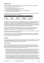
Expected range Predicting the range obtainable in any given situation is notoriously difficult since there are many factors involved. The main ones to consider are as follows: Type and location of antennas in use Type of terrain and degree of obstruction of the link path Sources of interference affecting the receiver “Dead” spots caused by signal reflections from nearby conductive objects Data rate and degree of filtering employed The following are typical examples – but range tests should always be performed before assuming that a particular range can be achieved in a given situation:...
Open the catalog to page 9
from any such circuitry and keep PCB track lengths to the minimum possible. A ground plane can be highly effective in cutting radiated interference and its use is strongly recommended. A simple test for interference is to monitor the receiver RSSI output voltage, which should be the same regardless of whether the microcontroller or other logic circuitry is running or in reset. The following types of integral antenna are in common use: Quarter-wave whip. This consists simply of a piece of wire or rod connected to the module at one end. At 151MHz the total length should be 471mm from module pin...
Open the catalog to page 10All Radiometrix catalogs and technical brochures
 LNM2H
LNM2H13 Pages
 VX2M
VX2M9 Pages
 WRX2C
WRX2C9 Pages
 MSR3
MSR38 Pages
 LMR0
LMR010 Pages
 SAT3
SAT35 Pages
 NTX2B
NTX2B13 Pages
 NTX0
NTX08 Pages
 MTX3
MTX310 Pages
 MTX2
MTX210 Pages
 BiM3H
BiM3H8 Pages
 QPX1
QPX18 Pages
 QPT1
QPT18 Pages
 AiM1
AiM19 Pages
 Universal Evaluation Kit
27 Pages
 TDL2A Evaluation Kit
4 Pages
 SPM2/RPM Evaluation Kit
7 Pages
 SP2 Evaluation Kit
12 Pages
 M48A Application Board
12 Pages
 M1144
M11448 Pages
 DXT / DXR
7 Pages
 Control44 Evaluation Kit
7 Pages
 CTA28 App. boards
11 Pages
 BL118
BL1187 Pages
 BD118
BD1185 Pages
 PAN1311
2 Pages
 PAN1310
2 Pages
 m48a
m48a11 Pages
 LMR2
LMR211 Pages
 TDL3F
TDL3F10 Pages
 krx2
krx29 Pages
 KTX2
KTX28 Pages
 RPM3
RPM315 Pages
 ENX1
ENX111 Pages
 NiM2
NiM211 Pages
 BiM1
BiM115 Pages
 RX3G
RX3G6 Pages
 PLR2
PLR212 Pages
 MSR3
MSR38 Pages
 CXR2
CXR212 Pages
 COR3
COR38 Pages
 TX2S
TX2S7 Pages
 CXT2
CXT212 Pages
 KRX2
KRX29 Pages
 KFX2
KFX24 Pages
 KDEC
KDEC5 Pages
 TXL2
TXL211 Pages
 Radiometrix
20 Pages


- Wireless remote control
- Industrial remote control
- Remote control with buttons
- Radio receiver
- On/off remote control
- Data transceiver
- Industrial receiver
- Industrial modem
- Serial receiver
- Multi-channel receiver
- Wireless receiver
- RS232 modem
- Data modem
- High-speed transceiver
- RS232 receiver
- Digital receiver
- Ethernet modem