
Catalog excerpts

M48A MODEM PRELIMINARY Issue 1,30 July 2012 The M48A is a half-duplex serial modem controller suitable for use with narrow band receivers, transmitters and transceivers. It supports a maximum transparent data throughput of 4800baud while baseband modulation frequencies do not exceed 3.2KHz. The device supports (programmable) long startup/preamble durations sometimes required for synthesized narrow band devices. Figure 1: M48A-000-DIL modem IC The M48 provides a half duplex link, but provided no two devices attempt to transmit at one time (a 'low' on RX_flow may be used as a primitive 'CTS' indication) no further restrictions on data transmission need be made, as all transmit timing, valid data identification and data stream buffering is conducted by the device. This unit supports a range of user interface data rates, in asynchronous data format: 1 start bit, 8 data bits, 1 stop bit. The supplied default (and the maximum transparent throughput) is 4800 baud To connect to a true RS232 device, inverting level shifters must be used (MAX232 type are ideal, but simple NPN transistor switches often suffice). With typical microcontrollers and uarts, direct connection is usable. Note that TXD has no internal pullup. Features ■ Operating voltage (temperature): 5V for standard version (-40°C to +85°C) ■ Maximum usage of the range capability of an RF module ■ Compatible with fast or slow transmitter power up timing requirements ■ 5kbps pulse duration coded protocol ■ Synchronisation codes and checksum to reduce false triggering on noise ■ Programmable transmit address and four receive addresses ■ Programmable timing parameters (preamble length, etc) ■ Programmable auxiliary serial output (to program radio modules) ■ Programmable serial modem baud rate (1200 - 76800 bps, half-duplex) ■ Suitable to be used with Narrow Band FM radio modules ■ Addressable point-to-point and point to multi point ■ Packet acknowledge/resend (ACK) mode ■ Store and forward repeater function Applications ■ PDAs, organisers & laptops ■ Handheld / portable terminals ■ Remote operated vehicles ■ Data loggers ■ In-building environmental monitoring and control ■ Industrial (SCADA) telemetry and M2M systems ■ Fleet management, vehicle data acquisition Evaluation platforms: M48 Application board Radiometrix Ltd M48A Modem Data Sh
Open the catalog to page 1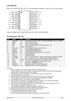
M48A is an 18pin PIC16F648A (SO, DIL), running proprietary software. It requires a 4.5v minimum supply. TONE OUT TONE IN OSC1 OSC2 Vdd (+5V) RX Inhibit TX Inhibit DFLT1 DFLTO Figure 2: package type, 18-Lead Plastic Dual In-line (PDIP - 300mil wide body) 1. M48 is intended for use with USX/UHX, RMX and LM series radios. If other radios are used, then to reliably recover the data format an external peak sampling data recovery circuit is recommended, such as QR96. 2. All conncetions are 5v cmos logic level except TXE, which is a an open drain (but do not exceed +5v on this pin) 3. Some...
Open the catalog to page 2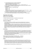
12. A simple addressing structure is included in the datastream. Units may be programmed onto one of 254 addresses Address 0 is a broadcast 'all units' address Address 255 is reserved (Units are supplied set to adr1 = 0, adr2,3,4 and adr_tx =1) 13. OSC1, 2 require a 19.6608MHz fundamental mode crystal, a series 100 ohm resistor from OSC2, and a pair of 15pF caps : from the crystal pins to 0V 14. DFLT0 DFTL1 high high : slow timing (20mS, 50mS, 20mS) low high : tba high low : tba high high : tba These pins have internal pullups. They are only read at power-up, if the unit has not been...
Open the catalog to page 3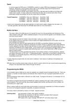
Speed In normal usage the M48 uses a 19.6608MHz crystal for a basic 4800 baud transparent throughput. However, elementary communication theory tells us that ultimate range and S/N performance (sensitivity) relates to bandwidth, and hence data rate. In applications where ultimate range matters more than a fast data path the M48 can be fitted with slower clock crystals. In these cases the fundamental link data rate is reduced (and other timing parameters scaled accordingly) but the link range will be increased. Crystal frequency Data rate 4800 baud Data rate 2400 baud Data rate 1200 baud Data...
Open the catalog to page 4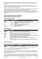
There is a 5 second timeout following the break within which the response must be sent , or the device reverts to data mode. An ASCII 1 (ctrl A) resets the timeout and generates a new @ and random character sequence. [ 'Break' conditions can be generated in several ways. Some terminal emulators have alt or ctrl key sequence. Dedicated hardware can be used to force a long (50-100mS) logic zero onto the TXD pin. Or an ASCII zero can be sent at a much lower baud-rate ] Once in setup mode, input bytes are stored in a 32 byte (maximum) command buffer and echoed back to the serial output. Space...
Open the catalog to page 5
of the data stream or uses the TX_flow signal. This pin allows the status of the transmit buffer to be monitored. It begins low. It goes high when the buffer reaches % full, and is then re-set (to low) when the buffer is empty again. It can be used to provide a simple 'CTS' signal. [ It is possible to 'lose track' of the baud rate of a unit while manually programming it. In this case an easy way of 'finding' the speed can be used: a byte should be sent to the device at each of the valid baud rates, and the echoed character monitored. Only at the correct rate will a correct echo be seen ] 1....
Open the catalog to page 6
Additional info on the M48 DIAG mode Takes effect when returning to data mode (an EXIT or <escape> command) The unit then does not output the received data burst. Instead, it outputs a status line whenever ANY valid M48 packet is received A:xx L:ll C:cc F:ff Where, xx destination address of the burst || length of the burst data payload (minus one) cc checksum byte value ff is a function byte, showing the status of the receiver decoder (ff=07 indicates a correct address and checksum match) DIAG mode is deactivated by either re-entering setup mode and executing a NORM command, or by...
Open the catalog to page 7
This function output a data packet to the transmitter, then returns to setup mode. The (length byte) is a single hex character. It sets the length of a transient data buffer, The actual buffer length is one more than the value of the length byte, so 0-F corresponds to a buffer between 1 and 16 bytes long The (data string) is a string of bytes equal in number to (length+1) After the length byte, the M48 sends back a colon character (ASCII 58) When the final byte is received, the modem goes into transmit, and sends the packet. By careful use of the & and $ command bytes, the M48 can be used...
Open the catalog to page 8All Radiometrix catalogs and technical brochures
-
LNM2H
13 Pages
-
NiM1B
13 Pages
-
VX2M
9 Pages
-
WRX2C
9 Pages
-
MSR3
8 Pages
-
LMR0
10 Pages
-
SAT3
5 Pages
-
NTX2B
13 Pages
-
NTX0
8 Pages
-
MTX3
10 Pages
-
MTX2
10 Pages
-
BiM3H
8 Pages
-
QPX1
8 Pages
-
QPT1
8 Pages
-
AiM1
9 Pages
-
Universal Evaluation Kit
27 Pages
-
TDL2A Evaluation Kit
4 Pages
-
SPM2/RPM Evaluation Kit
7 Pages
-
SP2 Evaluation Kit
12 Pages
-
M48A Application Board
12 Pages
-
M1144
8 Pages
-
DXT / DXR
7 Pages
-
Control44 Evaluation Kit
7 Pages
-
CTA28 App. boards
11 Pages
-
BL118
7 Pages
-
BD118
5 Pages
-
PAN1311
2 Pages
-
PAN1310
2 Pages
-
LMR2
11 Pages
-
TDL3F
10 Pages
-
krx2
9 Pages
-
KTX2
8 Pages
-
RPM3
15 Pages
-
ENX1
11 Pages
-
NiM2
11 Pages
-
BiM1
15 Pages
-
RX3G
6 Pages
-
PLR2
12 Pages
-
MSR3
8 Pages
-
CXR2
12 Pages
-
COR3
8 Pages
-
TX2S
7 Pages
-
CXT2
12 Pages
-
KRX2
9 Pages
-
KFX2
4 Pages
-
KDEC
5 Pages
-
TXL2
11 Pages
-
Radiometrix
20 Pages


