 Website:
Radiometrix
Catalog excerpts

M48 App Board Issue 2, 31 October 2012 The apps board presents the M48A, combined with a radio module (either USX or BiM/NiM family) and suitable interface circuits, power supplies and connectors. Optionally, the board can be housed in an EAS80 (or EAS120) extruded aluminium housing. In the simplest case, a pair of these units (with suitable aerials and power supplies connected, of course) can be connected directly to the serial ports of a pair of industrial PCs and the resulting wireless data link used without any further installation or oroarammina. The M48A is a simple, half duplex, transparent data link device. It provides a basic 4800 baud RS232 compatible path without the user needing to format, code, detect or otherwise worry about modifying his existing datastream or providing extra 'control' lines. The user interface datarate, addresses and operating parameters can all be easily reprogrammed via the serial port. It ought to be emphasised that the M48A is a very simple, easy to use, device. As supplied, it operates as a 4800 baud, transparent half-duplex data link. If required, there is an extensive range of programming options, allowing user interface speed from 1200 to 76800 baud, hardware flow control, one to one, one to many and broadcast addressing options, and acknowledge/re-transmit error handling protocols. Simple store and forward repeater operation is also provided. A good demonstration can be had by connecting a pair of PCs by their serial ports and a null-modem cable, and setting up terminal emulators (4800 baud, asynchronous, local echo on) on both computers. Confirm that good RS232 communication is present, and then replace the cable with a pair of M48A modems. The resulting 'radio teletype' can be entertaining to play with. Features ■ Maximum usage of the range capability of an RF module ■ Compatible with fast or slow transmitter power up timing requirements ■ 5kbps pulse duration coded protocol ■ Synchronisation codes and checksum to reduce false triggering on noise ■ Programmable transmit address and four receive addresses ■ Programmable timing parameters (preamble length, etc) ■ Programmable auxiliary serial output (to program radio modules) ■ Programmable serial modem baud rate (1200 - 76800 bps, half-duplex) ■ Suitable to be used with Narrow Band FM radio modules ■ Addressable point-to-point and point to multi point ■ Packet acknowledge/resend (ACK) mode ■ Store and forward repeater function Applications ■ PDAs, organisers & laptops ■ Handheld / portable terminals ■ Remote operated vehicles ■ Data loggers ■ In-building environmental monitoring and control ■ Industrial (SCADA) telemetry and M2M systems ■ Fleet management, vehicle data acquisition Radiometrix Ltd, M48A Apps board Ma
Open the catalog to page 1
User Interface Figure 2: DB9F RS232 connector pin arrangement Jumpers LK 1. link to hold unit permanently on (disables pin 6 switching) LK 2. link to enable rx dataflow inhibit (DTR) input. As supplied, all links are open Power This is a 2.1mm power connector. Centre pin is positive. Supply requirements are: 6-15v normal operation NOTES: 1. All Input pins will tolerate true +/- RS232 levels. No buffering is required. 2. The modem provides a half duplex link: Provided no two devices attempt to transmit at one time (a 'high' on RX_FLOW may be used as a primitive 'other user on channel'...
Open the catalog to page 2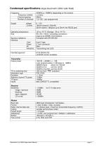
Radiometrix Ltd, M48A Apps board Manual page 3
Open the catalog to page 3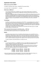
What does an M48A do ? In the simplest possible sense, the M48A is just a radio modem baseband device. It provides an interface between a user's asynchronous (“RS232 type”) serial port and the audio channel of a low power radio module. The M48 will transparently handle a half duplex serial stream at 4800 baud, buffering framing and coding the data into a baseband signal that a narrowband wireless module can handle. At the receive end it decodes the audio signal back into serial data. The timing requirements of the radio are allowed for with internal FIFO buffers, while the noisy imperfect...
Open the catalog to page 4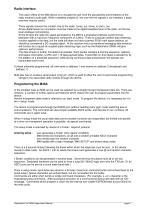
Radio interface The raison d'être of the M48 device is to insulate the user from the peculiarities and limitations of the radio module's audio path. While a detailed analysis of the over-the-link signals is not intended, a basic overview may be useful: Three signals connect the modem chip to the radio: tones_out, tones_in and n_txe. All are digital levels (so connection must be made to the digital baseband pins of the radio, not the low level analogue connections). At the bit-level the radio link signal generated by the M48 is a proprietary biphase (synchronous) bitstream with a maximum...
Open the catalog to page 5
The unit will only respond to certain command strings: Upper case characters are used for all commands Spaces are echoed, but are ignored by the parser Single character command Note: Variables dd, pp and oo are all two digit hexadecimal values (00 to FF). These timing parameters are immediately stored in E2PROM, and take effect right away. Radiometrix Ltd, M48A Apps board Manual page 6
Open the catalog to page 6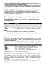
The timing commands directly affect the way the modem device controls the radio module. Beware! If they are set incorrectly then data errors or unreliable operation will result. The default settings are a safe, conservative setup for a typical 50mS set-up time multi-channel transceiver. For faster (usually single channel) radios the PREAM value can be reduced. Do not reduce this parameter too far, as it must deal with the settling times of the receiver data recovery circuit as well as the transmitter turn-on time. The DELAY and TXOFF parameters are primarily concerned with optimum channel...
Open the catalog to page 7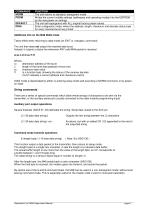
Additional info on the M48 DIAG mode Takes effect when returning to data mode (an EXIT or <escape> command) The unit then does not output the received data burst. Instead, it outputs a status line whenever ANY valid M48 packet is received A:xx L:ll C:cc F:ff Where, xx destination address of the burst || length of the burst data payload (minus one) cc checksum byte value ff is a function byte, showing the status of the receiver decoder (ff=07 indicates a correct address and checksum match) DIAG mode is deactivated by either re-entering setup mode and executing a NORM command, or...
Open the catalog to page 8All Radiometrix catalogs and technical brochures
-
LNM2H
13 Pages
-
NiM1B
13 Pages
-
VX2M
9 Pages
-
WRX2C
9 Pages
-
MSR3
8 Pages
-
LMR0
10 Pages
-
SAT3
5 Pages
-
NTX2B
13 Pages
-
NTX0
8 Pages
-
MTX3
10 Pages
-
MTX2
10 Pages
-
BiM3H
8 Pages
-
QPX1
8 Pages
-
QPT1
8 Pages
-
AiM1
9 Pages
-
Universal Evaluation Kit
27 Pages
-
TDL2A Evaluation Kit
4 Pages
-
SPM2/RPM Evaluation Kit
7 Pages
-
SP2 Evaluation Kit
12 Pages
-
M1144
8 Pages
-
DXT / DXR
7 Pages
-
Control44 Evaluation Kit
7 Pages
-
CTA28 App. boards
11 Pages
-
BL118
7 Pages
-
BD118
5 Pages
-
PAN1311
2 Pages
-
PAN1310
2 Pages
-
m48a
11 Pages
-
LMR2
11 Pages
-
TDL3F
10 Pages
-
krx2
9 Pages
-
KTX2
8 Pages
-
RPM3
15 Pages
-
ENX1
11 Pages
-
NiM2
11 Pages
-
BiM1
15 Pages
-
RX3G
6 Pages
-
PLR2
12 Pages
-
MSR3
8 Pages
-
CXR2
12 Pages
-
COR3
8 Pages
-
TX2S
7 Pages
-
CXT2
12 Pages
-
KRX2
9 Pages
-
KFX2
4 Pages
-
KDEC
5 Pages
-
TXL2
11 Pages
-
Radiometrix
20 Pages


