
Catalog excerpts

High Power Narrow Band Category 1 Radio Modem The LNM2H radio modem module offers a 500mW RF output 19200 data link with 3.3V TTL UART interface. It meet meets the ETSI Category 1 high performance receiver specification to be used where the operation of a SRD may have inherent safety of human life implications. Features Figure 1: LNM2H-458-19 Standard 458MHz (UK), 866MHz (India), 869MHz (EU) Available from 160MHz to 915MHz 12.5kHz / 25kHz channel spacing Narrow Band FM Multichannel Data rates up to 19200kbps ETSI EN 300 220-1 Category 1 High performance level receiver Point-to-Point, Point-to-Multipoint Store and Forward Repeater Mode with Dual Addressing to extend operating range Whitening of the data by XORing with a 9-bit pseudo-random (PN9) sequence 2-byte CRC checksum Digital Received Signal Strength Indicator (RSSI) Range Test Mode Safety-critical wireless applications such as social alarms and healthcare monitoring High-end security and fire alarms Lone Worker Alarms Industrial/Commercial Telemetry and Telecommand or Non-specific SRD usage In-building environmental monitoring and control Size: 47 x 34.5 x 7mm Operating frequencies: CH0:458.525, CH1:458.550,…CH15:458.900MHz Supply range: 5V DC Current consumption: 280mA TX Current consumption: 40mA RX RF baud rate: 300, 600, 1200, 2400, 4800, 9600, 19200bps (default). User baud rate: 300, 600, 1200, 2400, 4800, 9600 (default), 19200, 38400bps. Flow control: RTS/CTS, None (default) Modulation: 2-level GFSK [Binary], 4-level GFSK [Quaternary] (default) Transmit power: +27dBm (500mW) on 458MHz or +26dBm (400mW) on 869MHz 32MHz TCXO Reference with ±2.0ppm frequency stability over -30˚C +85˚C SAW front end filt
Open the catalog to page 1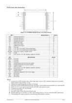
Figure 2: LNM2H/LNM3H Pinout and Dimensions PIN CS0 CS1 CS2 CS3 R B G RB4 TXD RXD RTS/DE CTS 3V3 PIN GPIO0 S0 RB5 PGC PGD GND 3V3 MCLR 0V 5V GND RF GND DESCIPTION Channel Select Bit 0 Channel Select Bit 1 Channel Select Bit 2 Channel Select Bit 3 RED LED output. BLUE LED output GREEN LED output Not used 3.3V TTL level UART Transmit Data Input 3.3V TTL level UART Received Data Output Serial Flow control or RS485 control UART Low current 3.3V LDO regulator output for reference DESCIPTION Not used Not used Not used Programming Clock for Firmware update Programming Data for Firmware update...
Open the catalog to page 2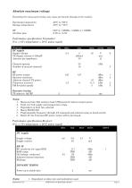
Absolute maximum ratings Exceeding the values given below may cause permanent damage to the module. Operating temperature Storage temperature Performance specifications Transmitter: (Vcc = 6V / temperature = 20C unless stated) General DC supply Supply voltage TX Supply current @ 500mW Antenna pin impedance Channel spacing Number of manual channels Dynamic timing TX select to full RF Notes: 1. 2. 3. 4. 5. 6. RF RF power output Spurious emissions Adjacent channel TX power Frequency accuracy FM deviation (peak) Measured into 50 resistive load, USB powered reduces output power. Total over...
Open the catalog to page 3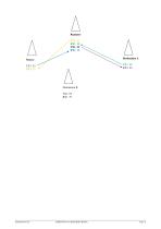
LNM2H Narrow Band Radio Modem
Open the catalog to page 4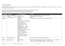
Configuration Mode LNM2H/LNM3H can be configured using serial AT Commands in Inverted RS232 (UART) format at 9600bps, 8 data bites, No Parity, 1 stop bit, No Flow control at 5V TTL level. Each command should be terminated with Enter Key / Carriage Returned (0x0D) to execute. Responses shown below in Italics will also be terminated with Carriage Retun. Following commands with ‘?’ as suffix can be used to check current setting. Command Function +++ Configuration Mode ATFACT Restore Factory DefaultSettings ATDEF? Exit Configuration Format, Response +++ ATFACT Response ATDEF? Channel = 0 RF...
Open the catalog to page 5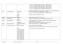
User Baud Rate Hardware Flow Control Read RSSI Append RSSI Frequency Band Channel Frequency LNM2H Narrow Band Radio Modem 2 level GFSK 2 level GFSK 2 level GFSK 2 level GFSK 2 level GFSK 20kHz bandwidth 12.5kHz bandwidth 12.5kHz bandwidth 12.5kHz bandwidth 12.5kHz bandwidth 4kHz Deviation 4kHz Deviation 4kHz Deviation 4kHz Deviation 4kHz Deviation Reducing RF Baud Rate increases Receive Sensitivity, hence operating range. Set User Data/Configuration Baud Rate to 9600bps 300, 600, 1200, 2400, 4800, 9600 (default), 19200, 38400bps Check current User Baud Rate setting Enable RTS/CTS hardware...
Open the catalog to page 6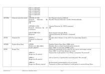
Channel selection mode ATC=11,869.4375 ATC=12,869.4625 ATC=13,869.4875 ATC=14,869.5125 ATC=15,869.5375 OK ATCHM =0 Channel Selection Hardware OK Set Channel selection Method By Parallel Channel Selection via Hex Switch (default) ATCHM=1 Channel Selection by ATCH command Channel Selection By AT OK Command OKATCHM? Response ATCH Packet Error Rate ATPER Packet error Rate Mode Good=1,Bad=0 Range Test ATRG=0 Range test Tx started Read channel selection Mode Channel Selection By Switch / Command OK Serially select channel 2 out of 00-15 as operating channel. OK Enables Packet Error Rate (PER)...
Open the catalog to page 7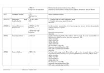
ATRG=3 Range test slave started ATV? Firmware version Addressing Enable/disable Unicast/Broadcast Trasmission ATDEU=xx Response ATDEU=FF Response LNM2H Narrow Band Radio Modem Bi directional communication acts as Slave Displays if valid packet is received from Master, transmits back to Master Read Firmware version 1 - Enable Point to Point Addressing mode 0 - Disable addressing mode (Default) OK In this unicast trasmission ,User can change the unicast address dynamically without storing in eeprom OK Broadcast transmission OK In Dual Addressing Mode, This address will be accept by next...
Open the catalog to page 8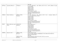
Read addressing mode ATAR? status Response Repeater mode LNM2H Narrow Band Radio Modem OK In dual addressing , this address will be the receive address of next repeater(RX2) ATX1=21 ARX1=32 ATX2=23 ARX2=XX No of repeater =xx Repeater disabled/Enabled P2P mode enabled/disabled OK In dual addressing ,this address will be the transmit address of transmitter(TX1)/repeater(TX2) ATX1=21 ARX1=32 ATX2=23 ARX2=12 No of repeater =xx Repeater disabled/Enabled P2P mode enabled/disabled OK Read module status ATX1=XX ARX1=XX ATX2=XX ARX2=XX No of repeater =xx Repeater disabled/Enabled P2P mode...
Open the catalog to page 9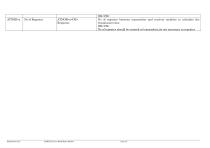
ATNOR=x Response LNM2H Narrow Band Radio Modem OK No of repeater between transmitter and receiver modules to calculate the trasmission time. OK No of repeater should be entered at transmitter,its not necessary in repeater
Open the catalog to page 10All Radiometrix catalogs and technical brochures
-
NiM1B
13 Pages
-
VX2M
9 Pages
-
WRX2C
9 Pages
-
MSR3
8 Pages
-
LMR0
10 Pages
-
SAT3
5 Pages
-
NTX2B
13 Pages
-
NTX0
8 Pages
-
MTX3
10 Pages
-
MTX2
10 Pages
-
BiM3H
8 Pages
-
QPX1
8 Pages
-
QPT1
8 Pages
-
AiM1
9 Pages
-
Universal Evaluation Kit
27 Pages
-
TDL2A Evaluation Kit
4 Pages
-
SPM2/RPM Evaluation Kit
7 Pages
-
SP2 Evaluation Kit
12 Pages
-
M48A Application Board
12 Pages
-
M1144
8 Pages
-
DXT / DXR
7 Pages
-
Control44 Evaluation Kit
7 Pages
-
CTA28 App. boards
11 Pages
-
BL118
7 Pages
-
BD118
5 Pages
-
PAN1311
2 Pages
-
PAN1310
2 Pages
-
m48a
11 Pages
-
LMR2
11 Pages
-
TDL3F
10 Pages
-
krx2
9 Pages
-
KTX2
8 Pages
-
RPM3
15 Pages
-
ENX1
11 Pages
-
NiM2
11 Pages
-
BiM1
15 Pages
-
RX3G
6 Pages
-
PLR2
12 Pages
-
MSR3
8 Pages
-
CXR2
12 Pages
-
COR3
8 Pages
-
TX2S
7 Pages
-
CXT2
12 Pages
-
KRX2
9 Pages
-
KFX2
4 Pages
-
KDEC
5 Pages
-
TXL2
11 Pages
-
Radiometrix
20 Pages


