LMR2
1 /11Pages

LMR2
1 /11Pages
Catalog excerpts

The LMT2 transmitter and LMR2 receiver modules offer a multi channel, low power, and reliable data link. This makes the LMT2/LMR2 pair ideally suited to those low power applications where existing wideband modules have insufficient range, or where low cost multichannel operation is needed without compromising on RF specification or regulatory requirement. ■ Conforms to EN 300 220-3 and EN 301 489-3 ■ High performance double superhet. PLL synthesizer with TCXO ■ quasi-dc (peak sampling) data recovery circuit (for enhanced performance on unbalanced datastreams) ■ SAW front-end filter ■ Data rates up to 5 kbps for standard module ■ Usable range over 1 km ■ Fully screened. Low profile ■ Feature-rich interface (RSSI, analogue and digital baseband) ■ Re-programmable via RS232 interface ■ Low power requirements Applications ■ Handheld terminals ■ EPOS equipment, barcode scanners ■ Data loggers ■ Industrial telemetry and telecommand ■ In-building environmental monitoring and control ■ High-end security and fire alarms ■ DGPS systems ■ Vehicle data up/download ■ Heavy vehicle/machinery controls Technical Summary ■ Operating frequency: 433.875-434.650MHz (EU band) 458.525 - 459.1MHz (UK band) ■ Other custom UHF bands ■ 32 channels ■ T ransmit power: +10dBm (10mW) / +20dBm (100mW) ■ Supply range: 3.1 - 15V (TX @ 10mW and RX), 4.1 - 15V (TX @ 100mW) ■ Current consumption: 34mA @ 10mW, 90mA @ 100mW (transmit) and 20mA (receive) ■ Data bit rate: 5kbps max. (standard module) ■ Receiver sensitivity: -118dBm (for 12 dB SINAD) ■ Serial configuration by inverted RS232 at 3V CMOS level Evaluation platforms: NBEK + LM Series carrier
Open the catalog to page 1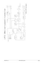
Radiometrix Ltd LMT2/LMR2 Data Sheet page 2
Open the catalog to page 2
1.6mm Figure 3: LMT2 footpint (top view) 1. Serial programming is by an inverted, CMOS logic level, 2400 baud RS232 datastream applied to the P0 pin. 2. Channel select inputs have pullups (50kQ) to 3v internal rail. Do not exceed 3V logic levels on this port. 3. Channel select inputs are active low 6. The pins 5a/b are not present, but are included in footprint for compatibility with other units in this family 7. In the 'off' state a PIN switch open circuits the RF output pin. There are no 'off' state spuri. 8. 10mW unit will operate (with marginally reduced specifications and lower (6-8mW) output...
Open the catalog to page 3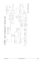
Figure 4: LMR2 block diagram Radiometrix Ltd
Open the catalog to page 4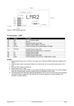
1.6mm Figure 5: LMR2 footpint (top view) 1. Serial programming is by an inverted, cmos logic level, 2400 baud RS232 datastream applied to the P0 pin. 2. Channel select inputs have pullups (50kQ) to 3v internal rail. Do not exceed 3v logic levels on this port. 3. Channel select inputs are active low 5. Data recovery circuit used for RXD is not a simple 'average and compare' type. It is a peak sampling quasi-DC coupled design, allowing a greater than usual flexibility in data format. 6. Unit will operate (with marginally reduced specifications) from a 3.0v rail. This must be well regulated and...
Open the catalog to page 5
aa = a two digit channel number from 00 to 31 nnnnn = synthesizer N register value (up to 65535) rrrr = synthesizer R register value (up to 16383) Note: A pause of at least 50ms must be allowed between command strings (EEPROM programming time). SINGLE mode does not store the N value in EEPROM. Therefore the unit is inoperative after a power down until either another valid SINGLE command is received, or mode is changed by a GOCHAN, SETPAR or SETSER command. SINGLE mode is intended for frequency agile applications. Radiometrix Ltd LMT2/LMR2 Data Sheet page 6
Open the catalog to page 6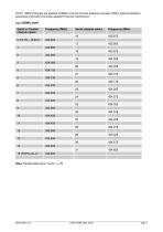
Radiometrix Ltd LMT2/LMR2 Data Sheet page 7
Open the catalog to page 7
Radiometrix Ltd LMT2/LMR2 Data Sheet page 8
Open the catalog to page 8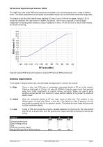
RX Received Signal Strength Indicator (RSSI) The LMR2 has wide range RSSI that measures the strength of an incoming signal over a range of 60dB or more. This allows assessment of link quality and available margin and is useful when performing range tests. The output on pin 5b of the module has a standing DC bias of up to 0.5V with no signal, rising to 2.5V at maximum indication (RF input levels of -40dBm and above). AVmin-max is typically 2V and is largely independent of standing bias variations. Output impedance is 40kQ. Pin 5b can drive a 100jjA meter directly, for simple monitoring. Three...
Open the catalog to page 9
The antenna choice and position directly controls the system range. Keep it clear of other metal in the system, particularly the 'hot' end. The best position by far, is sticking out the top of the product. This is often not desirable for practical/ergonomic reasons thus a compromise may need to be reached. If an internal antenna must be used, try to keep it away from other metal components, particularly large ones like transformers, batteries and PCB tracks/earth plane. The space around the antenna is as important as the antenna itself. 0.5 mm enameled copper wire close wound on 3.2 mm diameter...
Open the catalog to page 10
Copyright notice This product data sheet is the original work and copyrighted property of Radiometrix Ltd. Reproduction in whole or in part must give clear acknowledgement to the copyright owner. Limitation of liability The information furnished by Radiometrix Ltd is believed to be accurate and reliable. Radiometrix Ltd reserves the right to make changes or improvements in the design, specification or manufacture of its subassembly products without notice. Radiometrix Ltd does not assume any liability arising from the application or use of any product or circuit described herein, nor for any...
Open the catalog to page 11All Radiometrix catalogs and technical brochures
 LNM2H
LNM2H13 Pages
 NiM1B
NiM1B13 Pages
 VX2M
VX2M9 Pages
 WRX2C
WRX2C9 Pages
 MSR3
MSR38 Pages
 LMR0
LMR010 Pages
 SAT3
SAT35 Pages
 NTX2B
NTX2B13 Pages
 NTX0
NTX08 Pages
 MTX3
MTX310 Pages
 MTX2
MTX210 Pages
 BiM3H
BiM3H8 Pages
 QPX1
QPX18 Pages
 QPT1
QPT18 Pages
 AiM1
AiM19 Pages
 Universal Evaluation Kit
27 Pages
 TDL2A Evaluation Kit
4 Pages
 SPM2/RPM Evaluation Kit
7 Pages
 SP2 Evaluation Kit
12 Pages
 M48A Application Board
12 Pages
 M1144
M11448 Pages
 DXT / DXR
7 Pages
 Control44 Evaluation Kit
7 Pages
 CTA28 App. boards
11 Pages
 BL118
BL1187 Pages
 BD118
BD1185 Pages
 PAN1311
2 Pages
 PAN1310
2 Pages
 m48a
m48a11 Pages
 TDL3F
TDL3F10 Pages
 krx2
krx29 Pages
 KTX2
KTX28 Pages
 RPM3
RPM315 Pages
 ENX1
ENX111 Pages
 NiM2
NiM211 Pages
 BiM1
BiM115 Pages
 RX3G
RX3G6 Pages
 PLR2
PLR212 Pages
 MSR3
MSR38 Pages
 CXR2
CXR212 Pages
 COR3
COR38 Pages
 TX2S
TX2S7 Pages
 CXT2
CXT212 Pages
 KRX2
KRX29 Pages
 KFX2
KFX24 Pages
 KDEC
KDEC5 Pages
 TXL2
TXL211 Pages
 Radiometrix
20 Pages


- Wireless remote control
- Industrial remote control
- Remote control with buttons
- Bourn And Koch transceiver
- Radio receiver
- On/off remote control
- Data transceiver
- Industrial receiver
- Bourn And Koch radio transceiver
- Industrial modem
- Serial receiver
- Multi-channel receiver
- Wireless receiver
- RS232 modem
- Data modem
- High-speed transceiver
- Bourn And Koch microcontroller
- RS232 receiver
- Digital receiver
- Ethernet modem