 Website:
Radiometrix
Catalog excerpts

27MHz HF Narrow Band FM multi channel radio modules The LMT0 transmitter and LMR0 receiver modules offer a 10kHz channel spacing multi channel, low power, and reliable HF data link. This makes the LMT0/LMR0 pair ideally suited to those low power applications where existing wideband modules have insufficient range, or where low cost multi-channel operation is needed without compromising on RF specification or regulatory requirement. Figure 1: LMT0 transmitter and LMR0 receiver Conforms to EN 300 220-2 and EN 301 489-3 High performance double superhet. PLL synthesizer with TCXO 6 channels (standard). Up to 16 parallel select or 32 serial select channels quasi-dc (peak sampling) data recovery circuit (for enhanced performance on unbalanced datastreams) Data rates up to 4 kbps for standard module Usable range over 1km Fully screened. Low profile Feature-rich interface (RSSI, analogue and digital baseband) Re-programmable via UART interface Low power requirements Radio Control (R/C) Radio Service under FCC Part 95 subpart C Radio model control Telemetry and telecommand Wireless door entry systems Simple On/Off switching In-building environmental monitoring and control Security and fire alarms Vehicle/machinery controls Technical Summary Frequencies: 10mW 26.957-27.283MHz Non-specific Short Range Devices (SRD) 100mW 26.995, 27.045, 27.095, 27.145, 27.195, 27.255MHz Remote control Any 0.5MHz wide sub-band in 26-28MHz Transmit power: +10dBm (10mW) @ 4.1V; +20dBm (100mW) version also available Receiver sensitivity: -115dBm (for 12 dB SINAD) Supply range: 4.1V – 15V Transmitter 3.1V – 15V Receiver Current consumption: 40mA @ 10mW Transmit; 100mA @ 100mW Transmit 20mA Receive Data bit rate: 4kb
Open the catalog to page 1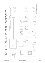
Figure 2: LMT0 block diagram Radiometrix Ltd
Open the catalog to page 2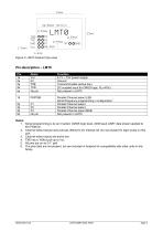
Figure 3: LMT0 footprint (top view) Function 4.1V – 15V power supply Ground Transmit Enable (active low) DC coupled input for CMOS logic. Rin=47k Not present in LMT0 Parallel Channel select LSB Serial frequency programming / configuration1 Parallel Channel select Parallel Channel select Parallel Channel select MSB Not present in LMT0 Notes: 1. Serial programming is by an inverted, CMOS logic level, 2400 baud UART data stream applied to the PGM pin. 2. Channel select inputs have pull-ups (50k) to 4V internal rail. Do not exceed 4V logic levels on this port. 3. Channel select inputs are...
Open the catalog to page 3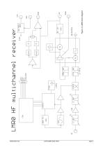
Figure 4: LMR0 block diagram Radiometrix Ltd
Open the catalog to page 4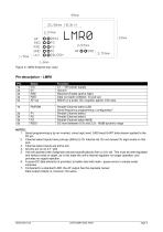
Figure 5: LMR0 footprint (top view) Function 3.1 – 15V power supply Ground Receiver Enable (active high) Data out (open collector, no pull-up) 600mV p-p audio. DC coupled, approx 0.8v bias. Parallel Channel select LSB Serial frequency programming / configuration1 Parallel Channel select Parallel Channel select Parallel Channel select MSB DC level between 0.5v and 2.2v. 60dB dynamic range NOTES: 1. Serial programming is by an inverted, cmos logic level, 2400 baud UART data stream applied to the P0 pin. 2. Channel select inputs have pull-ups (50k) to 3V internal rail. Do not exceed 3V logic...
Open the catalog to page 5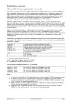
Serial interface commands 2400 baud UART. 8 bit data, no parity, 1 start bit, 1 or 2 stop bits. Serial data is sent to the unit on one of the parallel channel select pins (P0). It is very important that the unit does not 'decode' switch bounce in ordinary operation as a command string, or spurious re-writing of the e2prom will result. For this reason the user must send the 16 character string ENABLESERIALMODE (followed by a carriage return) to activate the serial command mode before sending any of the command strings listed below. Command mode is disabled on power down, or on reception of a...
Open the catalog to page 6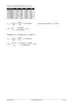
Default Transmitter and Receiver N, R values Frequency 26.995MHz 27.045MHz 27.095MHz 27.145MHz 27.195MHz 27.255MHz Comparison Frequency (fcomp) >10kHz
Open the catalog to page 7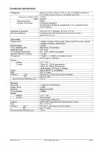
Condensed specifications Frequency Frequency stability LMT0 LMR0 Channel spacing Number of channels Operating temperature Spurious radiations Transmitter Output power Peak deviation TX on switching time Modulation type TX modulation bandwidth Adjacent channel TX power TX spurious Supply Voltage Current Inputs Size Interface User RF Recommended PCB hole size Receiver Sensitivity Image, Spurii Blocking LO re-radiation Supply Voltage Current Outputs Size Interface User RF Recommended PCB hole size 26.995, 27.045, 27.095, 27.145, 27.195, 27.255MHz (Standard) Any 0.5MHz wide sub-band in 26-28MHz...
Open the catalog to page 8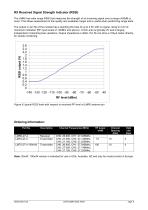
RX Received Signal Strength Indicator (RSSI) The LMR0 has wide range RSSI that measures the strength of an incoming signal over a range of 60dB or more. This allows assessment of link quality and available margin and is useful when performing range tests. The output on pin 5b of the module has a standing DC bias of up to 0.5V with no signal, rising to 2.2V at maximum indication (RF input levels of -40dBm and above). Vmin-max is typically 2V and is largely independent of standing bias variations. Output impedance is 40k. Pin 5b can drive a 100A meter directly, for simple monitoring. RF...
Open the catalog to page 9
Radiometrix Ltd Hartcran House 231 Kenton Lane Harrow, Middlesex HA3 8RP ENGLAND Tel: +44 (0) 20 8909 9595 Fax: +44 (0) 20 8909 2233 sales@radiometrix.com www.radiometrix.com Copyright notice This product data sheet is the original work and copyrighted property of Radiometrix Ltd. Reproduction in whole or in part must give clear acknowledgement to the copyright owner. Limitation of liability The information furnished by Radiometrix Ltd is believed to be accurate and reliable. Radiometrix Ltd reserves the right to make changes or improvements in the design, specification or manufacture of...
Open the catalog to page 10All Radiometrix catalogs and technical brochures
-
LNM2H
13 Pages
-
NiM1B
13 Pages
-
VX2M
9 Pages
-
WRX2C
9 Pages
-
MSR3
8 Pages
-
SAT3
5 Pages
-
NTX2B
13 Pages
-
NTX0
8 Pages
-
MTX3
10 Pages
-
MTX2
10 Pages
-
BiM3H
8 Pages
-
QPX1
8 Pages
-
QPT1
8 Pages
-
AiM1
9 Pages
-
Universal Evaluation Kit
27 Pages
-
TDL2A Evaluation Kit
4 Pages
-
SPM2/RPM Evaluation Kit
7 Pages
-
SP2 Evaluation Kit
12 Pages
-
M48A Application Board
12 Pages
-
M1144
8 Pages
-
DXT / DXR
7 Pages
-
Control44 Evaluation Kit
7 Pages
-
CTA28 App. boards
11 Pages
-
BL118
7 Pages
-
BD118
5 Pages
-
PAN1311
2 Pages
-
PAN1310
2 Pages
-
m48a
11 Pages
-
LMR2
11 Pages
-
TDL3F
10 Pages
-
krx2
9 Pages
-
KTX2
8 Pages
-
RPM3
15 Pages
-
ENX1
11 Pages
-
NiM2
11 Pages
-
BiM1
15 Pages
-
RX3G
6 Pages
-
PLR2
12 Pages
-
MSR3
8 Pages
-
CXR2
12 Pages
-
COR3
8 Pages
-
TX2S
7 Pages
-
CXT2
12 Pages
-
KRX2
9 Pages
-
KFX2
4 Pages
-
KDEC
5 Pages
-
TXL2
11 Pages
-
Radiometrix
20 Pages


