- Catalogs
- Radiometrix
- Control44 Evaluation Kit
Control44 Evaluation Kit
1 /7Pages

Control44 Evaluation Kit
1 /7Pages
Catalog excerpts

Control44 Evaluation Kit4 relay output with RF remote control Control44 Evaluation Kit enables user to evaluate Control44 Encoder/Decoder and appropriate single frequency Radiometrix module for a wireless remote control system. Radio modules can be assessed for their suitability in terms of range, price and operating frequency band. Range of Features Figure 1: Control44 Encoder (left) and Decoder (right) Evaluation Kits • 4-bit address, 4 bit data select switches • 4 relays to control mains powered devices rated up to 8A, 250VAC/30VDC • Visual indication of valid code received and active relays • RF module range testing • Push button for momentary control of relays • Momentary, Latched outputs • Dynamic relay state changes • Setup is simple as Plug-and-Play • RF Remote Control Demonstration • PP3 9V battery powered. Terminal block to prolong use with external power supply Kit Contents The CTR44 Evaluation Kit is supplied with the following contents: 2 CTR44-000-DIL 1 CTR44 Eval Kit PCB populated as Encoder (ENC) 1 CTR44 Eval Kit PCB populated as Decoder (DEC) 1 Single frequency Radiometrix Transmitter module (ordered separately) 1 Single frequency Radiometrix Receiver module (ordered separately) 2 1/4-wavelength monopole or helical antennas (ordered separately) 1 Data sheet of Radio module ordered • External power supply or 12V DC power adaptor for prolonged use • Electrical device to be controlled with a maximum rating of 8A, 30VDC or 250VAC • Electric Tester Screwdriver Radiometrix Ltd Control44 E-valuation Kit page 1
Open the catalog to page 1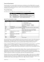
General Description Evaluation Kit uses a common PCB for both Encoder and Decoder just like CTR44-000 IC can be used as either Encoder or Decoder. However, the modes cannot be changed on the evaluation kit as PCBs are populated with necessary components for respective mode. Decoder PCB can be easily identified by the noticeable presence of relays. Visual Indication The following status LEDs will be activated depending on the status of CTR44. On-board low drop out regulator (LE50CZ) provides clean regulated 5V supply to the radio modules and microcontroller. However, the relay coils are powered...
Open the catalog to page 2
CTR44 Encoder Board In this mode, jumper link (JP1) connects the MODE pin of the CTR44-000-DIL to 5V supply line. RST pin is also tied to 5V. 5V supply to CTR44 IC is decoupled close to its VCC pin via 100nF Ceramic capacitor (C1). CTR44 has an internal weak pull-up to 5V on its Address and Data pins. Therefore the DIL switches when switched ON shorts the respective pin to 0V. Therefore, address/data bit values are inverted relative to switch positions. Address and Data Switch number starts from 1 instead of 0. (SW2 No 2=DB1) PNP transistor (T4) is used to Enable and supply power to SIL type...
Open the catalog to page 3
CTR44 Decoder Board It is populated with additional components to drive the Relay and provide visual indication of received data bits. NPN transistors (T3:T0) will provide the required drive current and voltage drop to activate relay coil to pull-in the internal relay switch and to activate the LEDs if the received data bit is ‘1’. Diodes (D7:D4) provide protection against back EMF developed by the relay coil when switching OFF. Since the STROBE pulse signal generated by the CTR44 is 10µs long, OK LED output may not be visible in bright sunlight. Setup 1) Insert the supplied Radiometrix Receiver...
Open the catalog to page 4
Figure 2: Schematic of CTR44 Evaluation Kit Radiometrix Ltd
Open the catalog to page 5
Figure 3: Component layout of CTR44 Evaluation Kit PCB Radiometrix Ltd Control44 E-valuation Kit page 6
Open the catalog to page 6
Copyright notice This product data sheet is the original work and copyrighted property of Radiometrix Ltd. Reproduction in whole or in part must give clear acknowledgement to the copyright owner. Limitation of liability The information furnished by Radiometrix Ltd is believed to be accurate and reliable. Radiometrix Ltd reserves the right to make changes or improvements in the design, specification or manufacture of its subassembly products without notice. Radiometrix Ltd does not assume any liability arising from the application or use of any product or circuit described herein, nor for any...
Open the catalog to page 7All Radiometrix catalogs and technical brochures
 LNM2H
LNM2H13 Pages
 NiM1B
NiM1B13 Pages
 VX2M
VX2M9 Pages
 WRX2C
WRX2C9 Pages
 MSR3
MSR38 Pages
 LMR0
LMR010 Pages
 SAT3
SAT35 Pages
 NTX2B
NTX2B13 Pages
 NTX0
NTX08 Pages
 MTX3
MTX310 Pages
 MTX2
MTX210 Pages
 BiM3H
BiM3H8 Pages
 QPX1
QPX18 Pages
 QPT1
QPT18 Pages
 AiM1
AiM19 Pages
 Universal Evaluation Kit
27 Pages
 TDL2A Evaluation Kit
4 Pages
 SPM2/RPM Evaluation Kit
7 Pages
 SP2 Evaluation Kit
12 Pages
 M48A Application Board
12 Pages
 M1144
M11448 Pages
 DXT / DXR
7 Pages
 CTA28 App. boards
11 Pages
 BL118
BL1187 Pages
 BD118
BD1185 Pages
 PAN1311
2 Pages
 PAN1310
2 Pages
 m48a
m48a11 Pages
 LMR2
LMR211 Pages
 TDL3F
TDL3F10 Pages
 krx2
krx29 Pages
 KTX2
KTX28 Pages
 RPM3
RPM315 Pages
 ENX1
ENX111 Pages
 NiM2
NiM211 Pages
 BiM1
BiM115 Pages
 RX3G
RX3G6 Pages
 PLR2
PLR212 Pages
 MSR3
MSR38 Pages
 CXR2
CXR212 Pages
 COR3
COR38 Pages
 TX2S
TX2S7 Pages
 CXT2
CXT212 Pages
 KRX2
KRX29 Pages
 KFX2
KFX24 Pages
 KDEC
KDEC5 Pages
 TXL2
TXL211 Pages
 Radiometrix
20 Pages


- Industrial remote control
- Remote control with buttons
- Bourn And Koch transceiver
- Radio receiver
- On/off remote control
- Data transceiver
- Industrial receiver
- Bourn And Koch radio transceiver
- Industrial modem
- Serial receiver
- Multi-channel receiver
- Wireless receiver
- RS232 modem
- Data modem
- High-speed transceiver
- RS232 receiver
- Digital receiver
- Ethernet modem