
- Catalogs
- Radiometrix
- BD118

BD118

BD118
- Relay Output: Rated up to 8A, 240VAC, SPDT changeover relay.
- Input: Active low logic input with pull-up to 5V and protection diodes.
- Power Supply: Available in 24V, 12V, and 5V versions, with a maximum current of 40mA plus relay coil current.
- RF Module: Compatible with any BiM pinout transceiver (e.g., RDL2, NiM2).
- Indicators: LEDs for power, relay state, and valid communication link.
- Addressing: User-programmable 8-bit address via DIP switch.
- Operating Temperature: -20 to +70 degrees Celsius (some radios limited to -10/+55).
- Size: 76 x 63 x 16mm, excluding connectors.
- 8-bit address select switch for easy configuration.
- Visual LED indicators for operational status.
- RF module range testing capability.
- Simple plug-and-play setup.
Catalog excerpts

These simple application boards use firmware based on the familiar CTA88 remote control systems to implement a bidirectional control link. A system consists of a master board (which initiates communication burst cycles) and a slave (which responds to them). In hardware terms these boards are the same, but have different firmware loaded. Figure 1: BD118 application boards A single relay output is provided on each board, controlled by a logic (or switch) input on the "opposite" board. This product only operates in one mode: the radio link operates continuously, and the output simply reflects the state of the input ("momentary" operation). The radio link uses a 10% duty cycle, 0.3 second burst cycle. The data format employed has an 8 bit address, which is set up on a DIP switch. LED indicators are provided for power, relay output state and "valid communication link established". (On the "master" this LED is lit constantly if the link is functional. On the "slave" board this LED blinks on with each burst received from the master) ■ 8 bit address select switch ■ A relay to control mains powered devices rated up to 8A, 240VAC ■ Visual LED indication of power, valid code received and active relay ■ RF module range testing ■ Logic or Switch input for momentary control of relay ■ Momentary relay output ■ Setup is simple as Plug-and-Play Kit Contents The BD118 Application kit is supplied with the following contents: 1 BD188 Encoder/Decoder Master board 1 BD188 Encoder/Decoder Slave board 2 Radiometrix Transceiver module (ordered separately) 2 1/4-wavelength monopole or helical antennas 1 BD118 Application board manual 1 Data sheet of Radio module ordered Additional requirement ■ External power supply (24V, 12V and 5V version available)
Open the catalog to page 1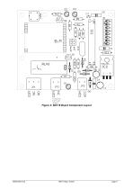
Closing Contact Input Figure 2: BD118 Board Component Layout
Open the catalog to page 3
Copyright notice This product data sheet is the original work and copyrighted property of Radiometrix Ltd. Reproduction in whole or in part must give clear acknowledgement to the copyright owner. Limitation of liability The information furnished by Radiometrix Ltd is believed to be accurate and reliable. Radiometrix Ltd reserves the right to make changes or improvements in the design, specification or manufacture of its subassembly products without notice. Radiometrix Ltd does not assume any liability arising from the application or use of any product or circuit described herein, nor for any...
Open the catalog to page 5All Radiometrix catalogs and technical brochures
 LNM2H
LNM2H13 Pages
 NiM1B
NiM1B13 Pages
 VX2M
VX2M9 Pages
 WRX2C
WRX2C9 Pages
 MSR3
MSR38 Pages
 LMR0
LMR010 Pages
 SAT3
SAT35 Pages
 NTX2B
NTX2B13 Pages
 NTX0
NTX08 Pages
 MTX3
MTX310 Pages
 MTX2
MTX210 Pages
 BiM3H
BiM3H8 Pages
 QPX1
QPX18 Pages
 QPT1
QPT18 Pages
 AiM1
AiM19 Pages
 Universal Evaluation Kit
27 Pages
 TDL2A Evaluation Kit
4 Pages
 SPM2/RPM Evaluation Kit
7 Pages
 SP2 Evaluation Kit
12 Pages
 M48A Application Board
12 Pages
 M1144
M11448 Pages
 DXT / DXR
7 Pages
 Control44 Evaluation Kit
7 Pages
 CTA28 App. boards
11 Pages
 BL118
BL1187 Pages
 PAN1311
2 Pages
 PAN1310
2 Pages
 m48a
m48a11 Pages
 LMR2
LMR211 Pages
 TDL3F
TDL3F10 Pages
 krx2
krx29 Pages
 KTX2
KTX28 Pages
 RPM3
RPM315 Pages
 ENX1
ENX111 Pages
 NiM2
NiM211 Pages
 BiM1
BiM115 Pages
 RX3G
RX3G6 Pages
 PLR2
PLR212 Pages
 MSR3
MSR38 Pages
 CXR2
CXR212 Pages
 COR3
COR38 Pages
 TX2S
TX2S7 Pages
 CXT2
CXT212 Pages
 KRX2
KRX29 Pages
 KFX2
KFX24 Pages
 KDEC
KDEC5 Pages
 TXL2
TXL211 Pages
 Radiometrix
20 Pages


- Wireless remote control
- Industrial remote control
- Remote control with buttons
- Radio receiver
- On/off remote control
- Data transceiver
- Industrial receiver
- Radio transceiver module
- Serial receiver
- Industrial modem
- Multi-channel receiver
- Wireless receiver
- RS232 modem
- High-speed transceiver
- Microcontroller
- Data modem
- RS232 receiver
- Digital receiver
- Ethernet modem