AiM1
1 /9Pages

AiM1
1 /9Pages
Catalog excerpts
flM) RADIOMETRIX We’re sorry, this linage Is temporarily The narrow band AiM1 transceiver offers a lo w power, reliable data link in a Radiometrix transceiver standard pin out and footprint. The AiM1 is a frequency programmable, narrowband design, suitable for licensed and unlicensed VHF allocations and 2M amateur band applications. Conforms to EN 300 220-3 and EN 301 489-3 (lOmW version only) ■ Standard frequency 144.390MHz ■ Other frequencies from 120MHz to 175MHz: see BiMI B ■ Data rates up to 5kbps for standard module ■ Usable range over 1 km ■ Low power requirements ■ 25kHz Channel spacing ■ Feature-rich interface (true analogue and/or digital baseband) The AiM1 is a half duplex radio transceiver module for use in long range bi-directional data transfer applications at ranges up to 1kilometres. AiM1 is available for operation on the amateur 144MHz band allocation as standard. AiM1 is also available as separate AiM1T transmitter and AiM1R receiver, which can be, used as dual-in-line equivalents of TX1 transmitter and RX1/NRX1 receiver respectively. Applications ■ Amateur radio ■ APRS systems ■ Packet operation ■ FM simplex telephony ■ Repeater monitoring Technical Summary ■ Fully integrated sigma-delta PLL synthesizer based design ■ High stability TCXO reference ■ Receiver sensitivity: -120dBm (for 12dB SINAD) ■ RSSI output with >50dBm range ■ Supply: 3.3V - 15V @ 30mA transmit, 18mA receive ■ Dimensions: 33 x 23 x 9mm Evaluation platforms: NBEK + BiM / SMX carrier Radiometrix Ltd., AiM1 transceiver data
Open the catalog to page 1
Figure 2: AiM1 schematics Radiometrix Ltd., AiM1 transceiver data sheet
Open the catalog to page 2
The transmit section of the AiM1 consists of a highly integrated sigma delta (fractional N) synthesizer based single chip RF device, configured over an SPI serial bus by an on-board microcontroller. The primary frequency reference for the transmitter is a 30MHz VC-TCXO. Modulation is applied directly to this reference via an AF baseband filter (rather than using the chip's internal modulator) to permit a wider range of baseband data rates and waveforms. Operation is controlled by the N_TXE line, the transmitter achieving full RF output typically within 5ms of this line being pulled low. The RF...
Open the catalog to page 3
Exceeding the values given below may cause permanent damage to the module. Performance specifications: (Vcc = 5V/ temperature = 20 °C unless stated) General DC supply Supply voltage TX Supply current (20mW) RX Supply current Antenna pin impedance RF centre frequency Channel spacing Number of channels Transmitter RF RF power output Spurious emissions Adjacent channel TX power Frequency accuracy FM deviation (peak) Baseband Modulation bandwidth @ -3dB TXD input level (logic low) TXD input level (logic high) Dynamic timing TX select to full RF Receiver RF/IF RF sensitivity @ 12dB SINAD RF sensitivity...
Open the catalog to page 4
1. Programs to any frequency with in the 120 - 175MHz range 2. Measured into 50Q. resistive loads. 3. Exceeds EN/EMC requirements at all frequencies. 4. 5ppm TCXO. Total over full supply and temperature range. 5. With 0V - 3.0V modulation input. 6. To achieve specified FM deviation. 7. See applications information for further details. 8. For received signal with ±3kHz FM deviation. Radiometrix Ltd., AiM1 transceiver data sheet Page 5
Open the catalog to page 5
Applications information Power supply requirements The AiM1 have built-in regulators which deliver a constant 3.3V to the transmitter and the receiver circuitry when the external supply voltage exceeds 3.3V. This ensures constant performance up to the maximum permitted rail, and removes the need for external supply decoupling, except in cases where the supply rail is extremely poor (ripple/noise content >0.1Vp-p). The unit will continue to function with a 3v supply, but power output will fall". TX modulation requirements The module is factory-set to produce the specified FM deviation with a TXD...
Open the catalog to page 6
Expected range Predicting the range obtainable in any given situation is notoriously difficult since there are many factors involved. The main ones to consider are as follows: • Type and location of antennas in use • Type of terrain and degree of obstruction of the link path • Sources of interference affecting the receiver • “Dead” spots caused by signal reflections from nearby conductive objects • Data rate and degree of filtering employed The following are typical examples - but range tests should always be performed before assuming that a particular range can be achieved in a given situation:...
Open the catalog to page 7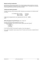
Module mounting considerations Good RF layout practice should be observed. If the connection between module and antenna is more than about 20mm long use 50Ω microstrip line or coax or a combination of both. It is desirable (but not essential) to fill all unused PCB area around the module with ground plane. Variants and ordering information The AiM1T transmitters, AiM1R receivers and AiM1 transceivers are manufactured in the following variants as standard: At 144.390MHz: AiM1-144.390-5 AiM1T-144.390-5 AiM1R-144.390-5 Transceiver Transmitter Receiver (These can be reprogrammed on any frequencies...
Open the catalog to page 8
Copyright notice This product data sheet is the original work and copyrighted property of Radiometrix Ltd. Reproduction in whole or in part must give clear acknowledgement to the copyright owner. Limitation of liability The information furnished by Radiometrix Ltd is believed to be accurate and reliable. Radiometrix Ltd reserves the right to make changes or improvements in the design, specification or manufacture of its subassembly products without notice. Radiometrix Ltd does not assume any liability arising from the application or use of any product or circuit described herein, nor for any...
Open the catalog to page 9All Radiometrix catalogs and technical brochures
 LNM2H
LNM2H13 Pages
 NiM1B
NiM1B13 Pages
 VX2M
VX2M9 Pages
 WRX2C
WRX2C9 Pages
 MSR3
MSR38 Pages
 LMR0
LMR010 Pages
 SAT3
SAT35 Pages
 NTX2B
NTX2B13 Pages
 NTX0
NTX08 Pages
 MTX3
MTX310 Pages
 MTX2
MTX210 Pages
 BiM3H
BiM3H8 Pages
 QPX1
QPX18 Pages
 QPT1
QPT18 Pages
 Universal Evaluation Kit
27 Pages
 TDL2A Evaluation Kit
4 Pages
 SPM2/RPM Evaluation Kit
7 Pages
 SP2 Evaluation Kit
12 Pages
 M48A Application Board
12 Pages
 M1144
M11448 Pages
 DXT / DXR
7 Pages
 Control44 Evaluation Kit
7 Pages
 CTA28 App. boards
11 Pages
 BL118
BL1187 Pages
 BD118
BD1185 Pages
 PAN1311
2 Pages
 PAN1310
2 Pages
 m48a
m48a11 Pages
 LMR2
LMR211 Pages
 TDL3F
TDL3F10 Pages
 krx2
krx29 Pages
 KTX2
KTX28 Pages
 RPM3
RPM315 Pages
 ENX1
ENX111 Pages
 NiM2
NiM211 Pages
 BiM1
BiM115 Pages
 RX3G
RX3G6 Pages
 PLR2
PLR212 Pages
 MSR3
MSR38 Pages
 CXR2
CXR212 Pages
 COR3
COR38 Pages
 TX2S
TX2S7 Pages
 CXT2
CXT212 Pages
 KRX2
KRX29 Pages
 KFX2
KFX24 Pages
 KDEC
KDEC5 Pages
 TXL2
TXL211 Pages
 Radiometrix
20 Pages


- Wireless remote control
- Industrial remote control
- Remote control with buttons
- Radio receiver
- On/off remote control
- Data transceiver
- Industrial receiver
- Industrial modem
- Serial receiver
- Multi-channel receiver
- Wireless receiver
- RS232 modem
- Data modem
- High-speed transceiver
- RS232 receiver
- Digital receiver
- Ethernet modem