


Series X Flexible Couplings Installation and Maintenance

Series X Flexible Couplings Installation and Maintenance
This document outlines the installation and maintenance guidelines for Series X flexible couplings, used in mechanical drive applications. The products adhere to the Machinery Directive 2006/42/EC and EN ISO 12100:2010 standards. A warranty covers defects for 12 months post-installation or 18 months post-shipment under recommended conditions.
Safety measures include guarding rotating parts, using ear protection, and careful handling of lubricants. Proper installation, maintenance, and storage are essential to prevent hazards like fire, noise, and mechanical damage. Electrical equipment should be isolated before maintenance.
These couplings compensate for misalignment but require precise alignment using a setting gauge. They are maintenance-free, with a maximum angular misalignment of 1½° and specific eccentricity limits detailed in Table A1.
Installation involves cleaning components, fitting keys, and aligning shafts. Taper-lock bushes require specific installation and removal procedures, including tightening screws to specified torques. Shaft alignment should be checked for angularity and eccentricity using block gauges and feelers.
These require careful hub assembly, shaft alignment, and sleeve connection. Lubrication is crucial for maintenance, and fully rigid couplings need precise shaft alignment.
This document provides technical specifications, installation procedures, and maintenance guidelines for the ELFLEX Pin and Bush Flexible Coupling Series X and ELIGN Gear Couplings, including alignment errors, installation steps, and maintenance schedules.
- Allowable misalignment for angularity and eccentricity is specified in tables B2 and C1.
- Recommended greases include Shell Silicone Grease, Dow Corning, and Rocol MX66 Silicone Grease.
- Torque specifications for pin bolts and flange bolts are provided in tables B3 and C2.
- Ensure all parts are clean and free from grit before installation.
- Apply silicon grease to rubber bush outer diameters and align coupling pin holes.
- Use a dial indicator for measuring eccentricity and ensure rigid support to avoid deflection.
- Align shafts using block gauge and feelers, and re-check alignment after the machine reaches operating temperature.
- Inspect rubber bushes every six months for wear and replace if necessary.
- Check alignment with pins removed and replace bushes as detailed in the installation section.
- Routine maintenance every 3000 hours or annually includes checking sleeve movement and grease levels.
- Scheduled maintenance every 8000 hours or biennially involves dismantling, cleaning, and inspecting gear teeth and seals.
- Align shafts as per Section 2 to achieve near-perfect alignment within specified limits.
- Avoid forcing coupling hub flanges together to prevent undue stresses.
- Use EP coupling grease (NLGI grade 1) and fill until it escapes through the horizontal position.
- Re-install filling plugs securely after lubrication.
Catalog excerpts

with you at every turn Series X - Flexible Couplings Installation & Maintenance with you at every turn
Open the catalog to page 1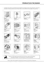
Serving an entire spectrum of mechanical drive applications from food, energy, mining and metal; to automotive, aerospace and marine propulsion, we are here to make a positive difference to the supply of drive solutions. Series A Worm Gear units and geared motors in single & double reduction types Series BD Screwjack worm gear unit Series BS Worm gear unit Series C Right angle drive helical worm geared motors & reducers Series F Parallel shaft helical geared motors & reducers Series G Helical parallel shaft & bevel helical right angle drive gear units Series H Large helical parallel shaft & bevel...
Open the catalog to page 2
INFORMATIONContents: Page Product Safety Information 2 Nylicon Flexible Couplings Assembly Details 4 Permissible Alignment Errors 4 Elflex Pin and Bush Flexible Couplings Installation of Hubs 6 Installation / Removal of Hubs with Taper Lock Bushes 6 Elign Gear Couplings Hub Assembly 12 Fully Rigid Couplings - Shaft Alignment 16 General Information Declaration of Conformity We hereby declare that our products have been designed in accordance with the following Directives and Standards: The Machinery Directive 2006/42/EC EN ISO 12100:2010 Safety of Machinery. General Principles...
Open the catalog to page 3
PRODUCT SAFETY INFORMATION Product Safety Information General - The following information is important in ensuring safety. It must be brought to the attention of personnel involved in the selection of the equipment, those responsible for the design of the machinery in which it is to be incorporated and those involved in its installation, use and maintenance. The equipment will operate safely provided it is selected, installed, used and maintained properly. As with any power transmission equipment proper precautions must be taken as indicated in the following paragraphs, to ensure safety. Potential...
Open the catalog to page 4
INSTALLATION & MAINTENANCE GEAR COUPLING WITH NYLON SLEEVE
Open the catalog to page 5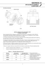
NYLICON COUPLING INSTALLATION OF NYLICON GEAR TYPE FLEXIBLE COUPLINGS Errors of alignment fall into categories of angularity and eccentricity, or a combination of both. While the NYLICON gear type flexible coupling compensates for a certain amount of misalignment, its life is greatly Increased if any errors present are reduced as much as possible. It is important, therefore to check the coupling for alignment with the setting gauge supplied before tightening the grub screws in the two hubs on their respective shafts. The gauge should be placed on the coupling as shown above. Check for angular...
Open the catalog to page 6
INSTALLATION & MAINTENANCE ELFLEX COUPLINGS FLEXIBLE PIN AND BUSH COUPLING
Open the catalog to page 7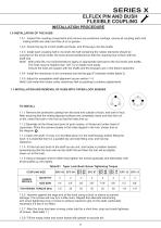
1.0.1 Inspect the coupling components and remove any protective coatings, ensure all coupling parts and mating shafts are clean and free of oil or grease. 1.0.2 Check the key fit in both shafts and hubs, and fit the keys into the shafts 1.0.3 Install each coupling half on its shaft, the half containing the rubber elements should be mounted on the driven shaft, the hubs should positioned so that the coupling face is flush with the shaft end Note! With press fits it is recommended to apply an appropriate lubricant to the hub bores and shafts, The hubs may be heated (max 120° C) to install more...
Open the catalog to page 8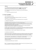
ELFLEX PIN AND BUSH FLEXIBLE COUPLING REMOVAL 1.1.9 Slacken all screws by several turns. Remove one (size 12 to 13, remove two) and insert it (them) into the jacking off holes shown thus in the diagram, after oiling thread and point of grub screws or thread and under head of cap screws. 1.1.10 Tighten the screw(s) until the bush is loosened in the hub and the assembly is free on the shaft. 1.1.11 Remove the assembly from the shaft. Check shaft alignment as follows:- Errors of alignment fall into categories of angularity (see figure 1) and eccentricity (See figure 2), or a combination of both....
Open the catalog to page 9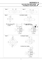
ELFLEX PIN AND BUSH FLEXIBLE COUPLING A 3b) Clock Gauge Method for Brake Drum Coupling 3c) Gauge Method for Brake Drum Coupling 4b) Brake Drum Coupling Setting Block
Open the catalog to page 10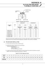
ELFLEX PIN AND BUSH FLEXIBLE COUPLING Table B2 Allowable Gap and Error
Open the catalog to page 11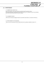
CONE RING FLEXIBLE COUPLING 4.0 4.1 RUBBER BUSH INSPECTION Check the condition of the rubber bushes periodically (every 6 months) for wear. If the outside diameter of the bushes is worn down more than 5% compared to the pin bore diameter, then the pin and bush assembles should be changed. With the pins removed an alignment check in accordance with Section 2.0 should be carried out. New pin and bush assemblies shall be fitted back into the coupling as detailed in section 3.0
Open the catalog to page 12
INSTALLATION & MAINTENANCE ELIGN COUPLINGS GEAR TYPE COUPLINGS
Open the catalog to page 13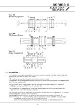
Type ER Single Engagement 1.1 Inspect the coupling components and remove any protective coatings. Ensure all coupling parts and mating shafts are clean and free of oil or grease. 1.2 Check that the keys fit correctly into both shafts and hubs (1) or (3) Coat each key with a grease resisting sealing compound (to prevent leakage of grease through the keyway) and fit the keys into the shafts 1.3 Apply a light coat of grease to the O-rings (8) and insert O-rings into grooves (X) in sleeves (2) on ES type couplings insert the O-rings into end caps (2a) 1.4 Place sleeves (2) over shaft ends, on ES...
Open the catalog to page 14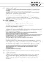
ELIGN GEAR COUPLING 1.0 HUB ASSEMBLY - cont.. 1.6 Coat the hub (1) & sleeve (2) gearing with coupling grease (see appendix ??) and place the sleeve over the hub 1.7 Install the machinery to be connected and set the gap (F) between shafts. Note! The gap can vary dependant on coupling size and type. See the table 3 or an approved drawing for the correct gap, - if in doubt pease contact our engineers. 1.8 Adjust machinery for acceptable shaft alignment as per section 2.0. Note! Use metal shim strips under machinery feet as packing to achieve adjustments. 1.9 Slide sleeve over the hub into position...
Open the catalog to page 15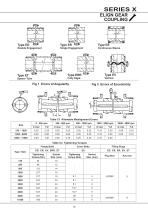
Double Engagement Single Engagement Type ES Continuous Sleeve Fig 1 Errors of AngularityFig 2 Errors of Eccentricity x. Table C1 Allowable Misalignment Errors Table C2 Tightening Torques Type / Size
Open the catalog to page 16All Radicon catalogs and technical brochures
 Series M Helical In-Line
116 Pages
 BR-Series-AM.
72 Pages
 adicon-SeriesX
32 Pages
 BR Series F
117 Pages
 Radicon Series X Couplings
32 Pages
 BR Series X Couplings
36 Pages
 BR Cone Ring Couplings
16 Pages
 Series J
73 Pages
 Motor
Motor4 Pages
 Series E Flyer
4 Pages
 G series
4 Pages
 BD
BD4 Pages
 Product Brochure radicon
8 Pages
 Benzlers Screw Jacks
69 Pages
 Series J - Shaft Mounted Gearbox
15 Pages
 Radicon Series ET
42 Pages
 BR Series G
71 Pages
 Metric
8 Pages
 Geared Pump
15 Pages
 Series P Planetary
4 Pages
 M series
120 Pages
 Sala Gears
74 Pages
 Screw Jacks
58 Pages
 Roloid Pump
17 Pages
 Heavy Duty Worm Gear Series ER
15 Pages
 SERIE G
71 Pages
 C series
120 Pages
 F series
119 Pages
 Series AM Worm Gear
73 Pages
 Worm Gear Series AJ
89 Pages
 Series BS Worm Gear
60 Pages
 Elflex Flexible Couplings
8 Pages
 Series H industrial gearboxes
123 Pages
 Geared Motor Series K
90 Pages
 Elign Gear Couplings
17 Pages


Archived catalogs
 Worm Gears Series AH
13 Pages


- Pump
- Industrial pump
- Pump with electric motor
- Stationary pump
- Seawater pump
- Electric gearmotor
- Planetary gearbox
- Coaxial gearhead
- Food product pump
- Right angle gearhead
- Direct current gear-motor
- Compact gearhead
- Solid-shaft gearhead
- Hollow-shaft gearhead
- Gearbox for industrial applications
- Transmission gearhead
- Industrial electric gearmotor
- Coaxial gearmotor
- Shaft gearhead