Series J
1 /73Pages

Series J
1 /73Pages
Catalog excerpts

Series J Shaft Mounted Gearbox
Open the catalog to page 1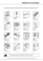
PRODUCTS IN THE RANGE Serving an entire spectrum of mechanical drive applications from food, energy, mining and metal; to automotive, aerospace and marine propulsion, we are here to make a positive difference to the supply of drive solutions. Series A Worm Gear units and geared motors in single & double reduction types Series BD Screwjack worm gear unit Series BS Worm gear unit Series C Right angle drive helical worm geared motors & reducers Series F Parallel shaft helical geared motors & reducers Series G Helical parallel shaft & bevel helical right angle drive gear units Series H Large helical...
Open the catalog to page 2
ATEX Compliance Assured Total compliance with the ATEX Directive safeguarding the use of industrial equipment in potentially explosive atmospheres is assured for users of our geared products. Certification is available for standard gearboxes and geared motors with badging displaying the ATEX zone, name and location of the manufacturer, designation of series or type, serial number, year of manufacture, Ex symbol and equipment group/category. ATEX directive 94/9/EC (also known as ATEX 95 or ATEX 100A) enforced in all EC member states. Compliance is compulsory for designers, manufacturers or suppliers...
Open the catalog to page 3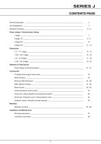
SERIES J CONTENTS PAGE General Description __________________________________________________________________ 3 Unit Designations ____________________________________________________________________ 4 Selection Procedure __________________________________________________________________ Power ratings / Thermal power ratings 1-stage _______________________________________________________________________ 7 2-stage 15:1 ___________________________________________________________________ Selection of V-belt drives Power ratings V-belt transmissions _________________________________________________...
Open the catalog to page 4
Series J Shaft Mounted Speed Reducers are high quality products, submitted to intense quality control and manufactured with the highest precision. — Worldwide after sales service — 19 types up to 600 kW, 57000 Nm — Wide range of standard accessories — High efficiency — Long gear and bearing lifetime — All mounting positions possible — Easy to mount — Easy to change speed through change of V-belt transmission — Space saving — Low noise level — Easy to service, due to standard components The shaft sleeve is supplied with tapped holes for dismounting the reducer as well as locking the reducer to...
Open the catalog to page 5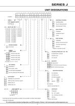
COOLING OPTIONS (ONLY J100 - 190) NO ADDITIONAL COOLING ELECTRIC FAN OIL COOLER 00' 00 LEFT ROTATION (Counter-Clockwise) 00 RIGHT ROTATION (Clockwise) MOUNTING POSITIONS H2 STANDARD H5 VERTICAL UP H6 VERTICAL DOWN H1 SPECIAL * SEE PAGE 68 * SPECIFY INCLINATION ETC INPUTSHAFT STANDARD MC - IEC FLANGE * HD - HYDRAULIC MOTOR * SPECIAL * SPECIFY MOTOR SIZE *THIS PAGE MAY BE PHOTOCOPIED ALLOWING THE CUSTOMER TO ENTER THEIR ORDER ** AVAILABLE ON REQUEST For online product selection/configuration and 2D/3D models of Series J visit www.benzlers.solidcomponents.com 4
Open the catalog to page 6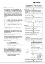
SERIES J SELECTION PROCEDURE Definition of service factor The torque ratings apply to service factor fb = 1.0. The service factor fb = 1.0 gives continual operation 4 to 8 hours a day at a uniform load without shocks and with 10 to 200 starts an hour. The moment of inertia of the driven machines is less than 20 % of the electric motor inertia and occasional peak torque may not exceed 1.8 times the torque rating. For other running conditions compensate with service factors according to tables. Mechanical Rating Determine the demand of power (Pe kW) or torque (Te Nm) and speed (ne min -1 ) to the...
Open the catalog to page 7
Service factors Table 1. Service factor fb
Open the catalog to page 8
Double reduction The torque is shown in Nm (1 Nm = 0.102 kpm = 0.7376 Ibf.ft)
Open the catalog to page 10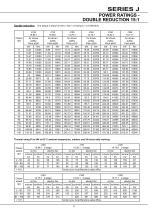
Double reduction The torque is shown in Nm (1 Nm = 0.102 kpm = 0.7376 Ibf.ft)
Open the catalog to page 11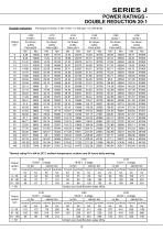
Double reduction The torque is shown in Nm (1 Nm = 0.102 kpm = 0.7376 ibf.ft)
Open the catalog to page 12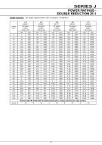
Double reduction The torque is shown in Nm (1 Nm = 0.102 kpm = 0.7376 Ibf.ft)
Open the catalog to page 13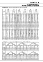
Double reduction The torque is shown in Nm (1 Nm = 0.102 kpm = 0.7376 ibf.ft)
Open the catalog to page 14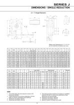
Please note: Dimensions R, T, T1, T2, T3 are not machined, deviations can occur. 1. The V-belt pulley should be placed as close to the housing as possible. 2. These dimensions are minimum diameters of driven pulley to prevent overloading of the bearings. 5. The reducer should normally be mounted on a shaftwith tolerance ISO js6. On heavy duty applications closer tolerances are recommended. 8. Space for spacer if locking ring is used.
Open the catalog to page 15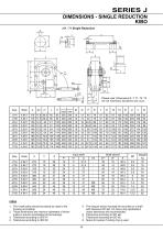
1. The V-belt pulley should be placed as close to the housing as possible. 2. These dimensions are minimum diameters of driven pulley to prevent overloading of the bearings. 5. The reducer should normally be mounted on a shaft with tolerance ISO js6. On heavy duty applications closer tolerances are recommended. 8. Space for spacer if locking ring is used.
Open the catalog to page 16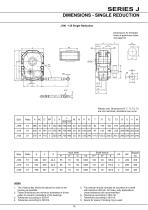
Dimensions for threaded holes at gearhouse sides, see page 53. Please note: Dimensions R, T, T1, T2, T3 are not machined, deviations can occur. 1. The V-belt pulley should be placed as close to the housing as possible. 2. These dimensions are minimum diameters of driven pulley to prevent overloading of the bearings. 5. The reducer should normally be mounted on a shaft with tolerance ISO js6. On heavy duty applications closer tolerances are recommended. 8. Space for spacer if locking ring is used.
Open the catalog to page 17
1. The V-belt pulley should be placed as close to the housing as possible. 2. These dimensions are minimum diameters of driven pulley to prevent overloading of the bearings. 5. The reducer should normally be mounted on a shaft with tolerance ISO h8. On heavy duty applications closer tolerances are recommended. 8. Space for spacer if locking ring is used.
Open the catalog to page 18
Please note: Dimensions R, T, T1, T2, T3 are not machined, deviations can occur. notes 1. The V-belt pulley should be placed as close to the housing as possible. 2. These dimensions are minimum diameters of driven pulley to prevent overloading of the bearings. 5. The reducer should normally be mounted on a shaft with tolerance ISO js6. On heavy duty applications closer tolerances are recommended. 8. Space for spacer if locking ring is used.
Open the catalog to page 19All Radicon catalogs and technical brochures
 Series M Helical In-Line
116 Pages
 BR-Series-AM.
72 Pages
 adicon-SeriesX
32 Pages
 BR Series F
117 Pages
 Radicon Series X Couplings
32 Pages
 BR Series X Couplings
36 Pages
 BR Cone Ring Couplings
16 Pages
 Motor
Motor4 Pages
 Series E Flyer
4 Pages
 G series
4 Pages
 BD
BD4 Pages
 Product Brochure radicon
8 Pages
 Benzlers Screw Jacks
69 Pages
 Series J - Shaft Mounted Gearbox
15 Pages
 Radicon Series ET
42 Pages
 BR Series G
71 Pages
 Metric
8 Pages
 Geared Pump
15 Pages
 Series P Planetary
4 Pages
 M series
120 Pages
 Sala Gears
74 Pages
 Screw Jacks
58 Pages
 Roloid Pump
17 Pages
 Heavy Duty Worm Gear Series ER
15 Pages
 SERIE G
71 Pages
 C series
120 Pages
 F series
119 Pages
 Series AM Worm Gear
73 Pages
 Worm Gear Series AJ
89 Pages
 Series BS Worm Gear
60 Pages
 Elflex Flexible Couplings
8 Pages
 Series H industrial gearboxes
123 Pages
 Geared Motor Series K
90 Pages
 Elign Gear Couplings
17 Pages


Archived catalogs
 Worm Gears Series AH
13 Pages


- Pump
- Industrial pump
- Pump with electric motor
- Stationary pump
- Seawater pump
- Electric gearmotor
- Planetary gearbox
- Coaxial gearhead
- Food product pump
- Right angle gearhead
- Direct current gear-motor
- Compact gearhead
- Solid-shaft gearhead
- Flexible coupling
- Hollow-shaft gearhead
- Gearbox for industrial applications
- Transmission gearhead
- Industrial electric gearmotor
- Shaft gearhead
- Coaxial gearmotor