Series J - Shaft Mounted Gearbox
1 /15Pages

Series J - Shaft Mounted Gearbox
1 /15Pages
Catalog excerpts

with you at every turn Series J - Shaft Mounted Gearbox Installation & Maintenance with you at every turn
Open the catalog to page 1
Installation of hollowshaft gear Installation of hollowshaft gear The hollowshaft gear is normally mounted on a shaft with js6 tolerance. The shaft bore has H7 tolerance. The gear unit is lifted using suitable holes for the purpose: J11-72, using torque arm hole, J100-190 using torque arm hole or lifting lug supplied. The shaft must be lubricated with Molycote BR2 or the supplied tube with copper grease, before fitting the gear unit. The gear unit must not be driven onto the shaft by force When fitting a pulley wheel without a compression bushing the threaded hole in the input shaft must be used....
Open the catalog to page 2
Installation of hollowshaft gear Recommended type of oil and grade of viscosity according ISO VG. Grade of viscosity ISO VG 68 EP ISO VG 220 EP ISO VG 220 Syntetic. At other ambient temperatures please contact Benzlers or the local representative. Oil quantities and oil level plugs. The figures in the first column under each respective mounting position, shown in the table, refer to the approximate quantities of oil for gear units mounted according to these positions. If it is required to mount a gear unit in any other position, Benzlers or your local representative should be consulted. Approximate...
Open the catalog to page 3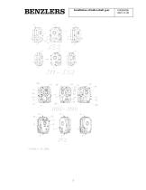
Installation of hollowshaft gear
Open the catalog to page 4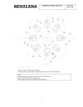
Installation of hollowshaft gear C40004GB 2001-11-05 L':i7004-:J5,clwg On J11-32 there is only one oil level plug. All Benzler-SALA speed reducers are prepared for syntetic oil type Polyalfaolefin. Note. Oil of mineral type should not be mixed with oil of syntetic type. Always check oil level when changing oil. SALA hollow shaft gears are supplied without lubricant.
Open the catalog to page 5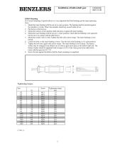
Installation of hollowshaft gear C40004GB 2001-11-05 KIBO-Mounting For Correct mounting of speed reducer it is very important that both bushings get the same squeezing force. 1. Mount the inner bushing with the nut in its outer position. The bushing shall be mounted against the shoulder or circlip. Where the shoulder should not exceed inside of nut. 3. Mount the reducer on the machine shaft and press it against the inner bushing. 4. Mount the outer bushing with the nut in it's inner position. Check that the bushing is not squeezed but the nut is in contact with the shaft sleeve. 5. Mount the...
Open the catalog to page 6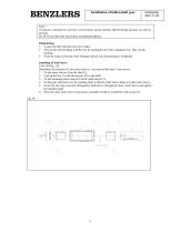
Installation of hollowshaft gear Note ! If reducer is mounted in a corrosive environment, ensure machine shaft bushings and nuts are oiled or greased. Do NOT use lubricants based upon molybdendisulphide. Dismounting 1. Loosen the bolt and take away the washer. 2. Pull out the outer bushing with the nut, by turning the nut with a adequate tool. Take out the bushing. 3. Press the reducer from the inner bushing with the nut, dismounting is completed. Installing of shaft sleeve J100-190 Fig . 1B Installation kit consists of 2 pcs insert sleeves, 1 pcs special key and 2 stop screws. 1. Fit the insert...
Open the catalog to page 7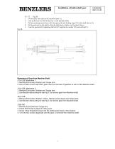
Installation of hollowshaft gear J11-72 Fig 2B 1. Fit the insert sleeve(4) on the machine shaft (1). 2. Line up the key (2) with the keyway in the machine shaft. 3. Fit the remaining insert sleeve (4), the spacer (6) and locking ring (33) in the shaft sleeve (5). 4. Fit the gear unit on the shaft so that the shaft sleeve slides over the insert sleeve. 5. Lock the gear unit by tightening the bolt (35) against the washer (31) and circlip(33) . Fig 2B Removing of Gear from Machine Shaft. J11A-32B, alternative 1. 1. Remove End screw, Washer and Torque arm. 2. Use a Puller of such size that it goes...
Open the catalog to page 8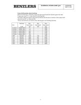
Installation of hollowshaft gear C40004GB 2001-11-05 General information about backstop. Before the backstop is fitted the torque and input speed should be checked against the table. Torque may reach 2,5 x value shown for brief periods. See hollow shaft gear against input shaft and decide the direction of rotation of the output shaft: anticlockwise BV, or clockwise BH. Always state direction of rotation when ordering gear unit including backstop.
Open the catalog to page 10
Installation of hollowshaft gear C40004GB 2001-11-05 Instructions for backstop J12-32 Installation Fig.6 Permissible working temperature in steady operation -30° C -+100° C. Backstop supplied with corrosion protection DO NOT REMOVE. 1. Remove the cover (14) from the gear. 2. Decide the direction of rotation for the backstop (29:7) and slide it onto the shaft(1) against the gear casing bearing. The backstop must be slided on and inserted by hand. In no case strong violence may be used. If a small force is required apply it both on inner and outer race in accordance with general bearing assembly....
Open the catalog to page 11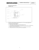
Installation of hollowshaft gear Instructions for backstop J52-72 Installation Fig 9. Permissible working temperature in steady operation -30º C -+100º C. Backstop supplied with corrosion protection DO NOT REMOVE. 1. Remove cover (14) from the gear. 2. Fit the support ring (28:3) against the bearing.(Only applies to J52) 3. Grease the shaft on which the backstop is to be mounted and fit the key (28:5) in the shaft keyway. In case of J72, fit also locking ring (28:7). 4. Determine the direction of rotation of the backstop (28:1) and slide this onto the shaft (1). 5. Fit the key (28:4) in the cover...
Open the catalog to page 12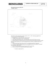
Installation of hollowshaft gear Instruction for back stop J100-J190 Assembly se fig 10. Permissible working temperature in steady operation -30º C -+100º C. Backstop supplied with corrosion protection DO NOT REMOVE. 1. Dismantle the cover part (30:1*) from standard reducer. 2. Assembly the snap ring part (30:3*) in gear housing. 3. Grease shaft end where back stop is to be fitted and put Key part (30:2*)into the keyway. 4. Determine direction of rotation and remove outer race part (30:4*)of backstop and and fit it gently against the snap ring part (30:3*) in gear housing.(Direction of rotation...
Open the catalog to page 13
FINLAND Oy Benzler AB Vanha Talvitie 3C FI-00580 Helsingfors, Finland Tel: +358 9 340 1716 AUSTRALIA Radicon Transmission (Australia) PTY Ltd Australia Tel: +61 421 822 315 EUROPE Benzler TBA BV Jachthavenweg 2 NL-5928 NT Venlo Germany Tel: 0800 350 40 00 THAILAND Radicon Transmission (Thailand) Ltd 700/43 Moo 6 Amata Nakorn Industrial Estate Tumbol Klongtumru Muang, Chonburi 20000 Thailand Tel: +66 3845 9044 UNITED KINGDOM Radicon Transmission UK Ltd Unit J3 Lowfields Business Park, Lowfields Way, Elland West Yorkshire, HX5 9DA Tel: +44 1484 465 800 USA Radicon Drive Systems, Inc. 2475...
Open the catalog to page 14All Radicon catalogs and technical brochures
 Series M Helical In-Line
116 Pages
 BR-Series-AM.
72 Pages
 adicon-SeriesX
32 Pages
 BR Series F
117 Pages
 Radicon Series X Couplings
32 Pages
 BR Series X Couplings
36 Pages
 BR Cone Ring Couplings
16 Pages
 Series J
73 Pages
 Motor
Motor4 Pages
 Series E Flyer
4 Pages
 G series
4 Pages
 BD
BD4 Pages
 Product Brochure radicon
8 Pages
 Benzlers Screw Jacks
69 Pages
 Radicon Series ET
42 Pages
 BR Series G
71 Pages
 Metric
8 Pages
 Geared Pump
15 Pages
 Series P Planetary
4 Pages
 M series
120 Pages
 Sala Gears
74 Pages
 Screw Jacks
58 Pages
 Roloid Pump
17 Pages
 Heavy Duty Worm Gear Series ER
15 Pages
 SERIE G
71 Pages
 C series
120 Pages
 F series
119 Pages
 Series AM Worm Gear
73 Pages
 Worm Gear Series AJ
89 Pages
 Series BS Worm Gear
60 Pages
 Elflex Flexible Couplings
8 Pages
 Series H industrial gearboxes
123 Pages
 Geared Motor Series K
90 Pages
 Elign Gear Couplings
17 Pages


Archived catalogs
 Worm Gears Series AH
13 Pages


- Pump
- Industrial pump
- Pump with electric motor
- Stationary pump
- Seawater pump
- Electric gearmotor
- Planetary gearbox
- Coaxial gearhead
- Food product pump
- Right angle gearhead
- Direct current gear-motor
- Compact gearhead
- Solid-shaft gearhead
- Flexible coupling
- Hollow-shaft gearhead
- Gearbox for industrial applications
- Transmission gearhead
- Industrial electric gearmotor
- Shaft gearhead
- Coaxial gearmotor