


Series H industrial gearboxes

Series H industrial gearboxes
The Series H gear units are available in both in-line and right-angle versions, offering single to quadruple reduction gear stages with a power capacity exceeding 8300 kW. The modular design ensures high interchangeability of parts, leading to production economies while maintaining component integrity. The range includes 11 sizes with ratios from 1.22:1 to 130:1, fully metric with standardized shaft extensions and output shaft bores.
Key features include profile ground helical gears for quiet operation, options for horizontal or vertical mounting, and special designs for cooling tower or heavy-duty stirrer applications. Units can have hollow bores for output shaft mounting, and improvements in design are ongoing. Shaft mounted units can be mounted on the driven machine shaft extension or on a baseplate. Motorized gear units are available with British Standard metric flanged motors. Baseplates are designed for stiffness and correct alignment. Holdbacks are available for non-reversing drives, and units are shipped without oil but with rust protection.
Units are designated by type of gears (helical or bevel helical), number of reductions, and mounting type (foot or shaft mounted). When ordering, information required includes prime mover type, driven machine details, gear unit specifications, and shaft connections.
All geared products comply with the ATEX Directive for use in potentially explosive atmospheres, with certification available for standard gearboxes and motors. Compliance is mandatory for equipment used in hazardous locations.
Lubrication is typically by oil transfer via gears, with spray lubrication available for high-speed applications. Cooling methods include convection, fans, cooling coils, and separate oil coolers. Oil change periods vary based on lubricant type and temperature.
Various sealing arrangements are available, including oil lip seals, labyrinth seals, and flingers, depending on the unit size and application requirements.
Basic ratings are based on standard operating conditions, with factors provided to adjust for different service conditions. Gear unit selection involves determining the required power capacity and selecting the appropriate gearbox type and ratio.
The required power for a gear unit is calculated using the formula: Required power (PR) = Absorbed power (Pa) x Mechanical Service Factor (Fm). The document provides tables for determining the mechanical service factor based on the duration of service and type of load (uniform, moderate shock, heavy shock).
Applications are classified by load type: Uniform (U), Moderate shock (M), and Heavy shock (H). This classification helps in selecting the appropriate gear unit and service factors.
Selection involves determining the type of unit and required power, then choosing the appropriate size from gear unit rating tables. Adjustments for mechanical rating are made based on service conditions, including the number of starts and whether the unit is reversing.
After selecting a gear unit mechanically, its thermal capacity must be verified. The basic thermal rating capacity is adjusted for operating conditions using factors such as ambient temperature, duty cycle, air velocity, and altitude. The adjusted thermal capacity (PTC) must exceed the absorbed power (Pa) for the unit to be acceptable.
Several tables provide adjustment factors for ambient temperature, intermittent duty, air velocity, and altitude. These factors are crucial for ensuring the gear unit operates efficiently under specific environmental conditions.
The document includes examples illustrating the selection process for different gear unit types and applications. Each example details the calculation of mechanical and thermal capacities, adjustment factors, and the final selection of gear units.
This document serves as a comprehensive guide for selecting and evaluating gear units, ensuring they meet the mechanical and thermal requirements of various industrial applications.
This section lists various lubricants approved for use, specifying their ambient temperature ranges and minimum operating temperatures. It highlights the importance of not operating below the recommended temperatures and provides notes on specific lubricant characteristics, such as their effects on certain components and compatibility with devices like trailing sprags or holdback devices.
Details different mounting versions for various units, including foot-mounted and shaft-mounted options, with specifications for single, double, and triple reduction units. It categorizes units based on their application, such as cooling tower drives and heavy-duty stirrer drives.
Provides dimensions for output shafts and bores, including both metric and American standards. It includes details on coupling sizes and the flexibility of cone ring flexible couplings, which accommodate misalignment and provide torsional flexibility.
Tables outline permissible overhung and axial loads on shafts for various unit sizes and speeds. It includes factors for calculating overhung loads and notes on the direction of load and specific applications like heavy-duty stirrer drives.
Guidance on calculating the bending moment on gearbox output shafts, emphasizing the importance of using precise values when available. It confirms the suitability of standard and heavy-duty units for supporting paddles directly coupled to the gearbox output shaft.
Catalog excerpts

Series H Industrial Gearbox Industrial Gearbox CH-2.00GB1211
Open the catalog to page 1
PRODUCTS IN THE RANGE Serving an entire spectrum of mechanical drive applications from food, energy, mining and metal; to automotive, aerospace and marine propulsion, we are here to make a positive difference to the supply of drive solutions. Series A Worm Gear units and geared motors in single & double reduction types Series BD Screwjack worm gear unit Series BS Worm gear unit Series C Right angle drive helical worm geared motors & reducers Series F Parallel angle helical bevel helical geared motors & reducers Series G Helical parallel shaft & bevel helical right angle drive gear units Series...
Open the catalog to page 2
ATEX Compliance Assured Total compliance with the ATEX Directive safeguarding the use of industrial equipment in potentially explosive atmospheres is assured for users of our geared products. Certification is available for standard gearboxes and geared motors with badging displaying the CE Mark and the Ex mark, name and location of the manufacturer, designation of series or type, serial number, year of manufacture, Ex symbol and equipment group/category. ATEX directive 94/9/EC (also known as ATEX 95 or ATEX 100A) and the CE Marking Directive are enforced in all EC member states. Compliance is...
Open the catalog to page 3
CONTENTS 9709 General Description 1 Unit Designations & Ordering 2 Design Features Shaft Sealing Arrangements Explanation and use of Ratings and Service Factors 3-4 5 6-9 Selection Procedure 10 - 12 Exact Ratios 13 - 14 Lubrication 15 - 17 Mounting Versions 18 Outputshaft Options 19 Outputbore Options 20 Series X Couplings 21 REDUCER Overhung & Axial Loads on Shafts 23 - 26 Moments of Inertia 27 - 28 Ratings - Input Power / Output Torque 29 - 88 Dimension Sheets - Speed Reducers 89 - 106 Customer Outputshaft and Shrink Disk Details 107 - 108 Cooling Coil Connections 109 Holdbacks 110 Torque Arm...
Open the catalog to page 4
GENERAL DESCRIPTION 9606 Radicon Series H Series H gear units are available in in-line and right angle versions in single, double, triple and quadruple reduction gear stages having a maximum power capacity exceeding 8300 kW. The modular design and construction of the Series H offers many engineering and performance benefits including a high degree of interchangeability of parts and sub assemblies. This in turn provides considerable economies of production whilst maintaining the highest standard of component integrity Single reduction Foot mounted parallel shafts * H 1 1 4 0 Double reduction Shaft...
Open the catalog to page 5
UNIT DESIGNATIONS & ORDERING 9606 1 2 B 3 3 4 5 6 7 M 2 8 0 * EXAMPLE OF TYPE 1- TYPE OF GEARS 5,6,7- SIZE OF UNIT H B 2- 1 - HELICAL GEARS ONLY 4 THROUGH 4 - HELICAL & BEVEL HELICAL GEARS NO OF REDUCTIONS 1 THROUGH 4- TYPE OF UNIT 3 M 3- 0 REDUCER UNIT - MOTORISED UNIT VERSION - FOOT MOUNTED S - SHAFT MOUNTED S F - FOOT/SHAFT MOUNTED INFORMATION REQUIRED WHEN ORDERING UNITS PRIME MOVER - Type - electric motor or engine, for example 4 cylinder internal combustion engine - Power rating in kW - Output speed. if variable, indicate speed range and frequency of variation - Dimensions of prime mover...
Open the catalog to page 6
DESIGN FEATURES 9606 Shaft Mounted Units Shaft mounted units are of two designs, the first of which is mounted on the driven machine shaft extension and connected to the foundation by torque arm, supplied as an optional extra. Additionally, the foot/shaft design is available for mounting on a baseplate with motor and coupling, the complete assembly being mounted on the driven machine shaft extension and connected to the foundation by a torque arm. All gear units are fitted with a 'shrink disc' device to provide positive clamping on the driven machine shaft extension. It is positioned on the input...
Open the catalog to page 7
DESIGN FEATURES 9707 Gears High quality alloy case hardening materials provide long life wear resistance and fatigue strength. Profile ground single helical gears and spiral bevel gears lapped in pairs ensure high standards of accuracy, surface finish and quiet running characteristics. Helical gears are fitted in parallel shaft units with shafts at right angles incorporate spiral bevel and helical gears. Bearings Roller bearings are used throughout. Gearcases Gearcases are of rigid cast iron construction with modern styling. Casings are split in the horizontal plane. Inspection covers are provided...
Open the catalog to page 8
SHAFT SEALING ARRANGEMENTS 9706 SHAFT SEALING ARRANGEMENTS OF HORIZONTAL MOUNTED GEAR UNITS Oil seal lip Labyrinth and Oil seal Labyrinth and Flinger Labyrinth, Flinger and Oil seal Type Shaft Unit Size 140 160 180 200 225 250 280 315 355 400 450 Input B3 Ouput <- - - - - - - - - - - - - - - - - - - - - - - - - Labyrinth and Oil seal - - - - - - - - - - - - - - - - - - - - - - - - - - > <- - - - - - - - - - - - - - - - - - - - - - - - - - - - - - Oil lip seal - - - - - - - - - - - - - - - - - - - - - - - - - - - - - > Ouput <- - - - - - - - - - - - - - - - - - - - - - - - - Labyrinth and Oil...
Open the catalog to page 9
EXPLANATION AND USE OF RATINGS AND ASSOCIATED RATING FACTORS 9709 1.0 Basic Ratings The catalogue mechanical and thermal rating capacity of the Series H gear units are based on a standard set of service operating conditions. The conditions are: i) The unit operates at a uniform absorbed power for 10 hours per day and with no more than one unidirectional start per hour at twice the absorbed power at input shaft to the gear unit. ii) It operates in a large indoor space at an ambient temperature of 20oC with ambient air velocity of 1.4m/sec. iii) The sump bulk oil temperature is 110oC when transmitting...
Open the catalog to page 10
EXPLANATION AND USE OF RATINGS AND ASSOCIATED RATING FACTORS 9606 Driven Machine type of load Table 2. Load Classification by Applications Cranes main hoists bridge travel trolley travel U U Crusher ore stone sugar H H H Dredges cable reels conveyors cutter head drives jig drives manoeuvring winches pumps screen drive stackers utility winches M M H H M M H M M = Uniform load M = Moderate shock load H = Heavy shock load = Refer to Driven Machine type of load Agitators pure liquids liquids and solids liquids-variable density U M M Blowers centrifugal lobe vane U M U Brewing and distilling bottling...
Open the catalog to page 11All Radicon catalogs and technical brochures
 Series M Helical In-Line
116 Pages
 BR-Series-AM.
72 Pages
 adicon-SeriesX
32 Pages
 BR Series F
117 Pages
 Radicon Series X Couplings
32 Pages
 BR Series X Couplings
36 Pages
 BR Cone Ring Couplings
16 Pages
 Series J
73 Pages
 Motor
Motor4 Pages
 Series E Flyer
4 Pages
 G series
4 Pages
 BD
BD4 Pages
 Product Brochure radicon
8 Pages
 Benzlers Screw Jacks
69 Pages
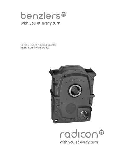 Series J - Shaft Mounted Gearbox
15 Pages
 Radicon Series ET
42 Pages
 BR Series G
71 Pages
 Metric
8 Pages
 Geared Pump
15 Pages
 Series P Planetary
4 Pages
 M series
120 Pages
 Sala Gears
74 Pages
 Screw Jacks
58 Pages
 Roloid Pump
17 Pages
 Heavy Duty Worm Gear Series ER
15 Pages
 SERIE G
71 Pages
 C series
120 Pages
 F series
119 Pages
 Series AM Worm Gear
73 Pages
 Worm Gear Series AJ
89 Pages
 Series BS Worm Gear
60 Pages
 Elflex Flexible Couplings
8 Pages
 Geared Motor Series K
90 Pages
 Elign Gear Couplings
17 Pages


Archived catalogs
 Worm Gears Series AH
13 Pages


- Industrial pump
- Pump with electric motor
- Stationary pump
- Seawater pump
- Electric gearmotor
- Planetary gearbox
- Coaxial gearhead
- Food product pump
- Right angle gearhead
- Direct current gear-motor
- Compact gearhead
- Solid-shaft gearhead
- Hollow-shaft gearhead
- Gearbox for industrial applications
- Transmission gearhead
- Industrial electric gearmotor
- Coaxial gearmotor
- Shaft gearhead