


SERIE G

SERIE G
The Series G Industrial Reducers are versatile gear units designed for various mechanical drive applications across industries such as food, energy, mining, metal, automotive, aerospace, and marine propulsion. They are available in parallel shaft helical and right angle shaft bevel/helical configurations, with a maximum output torque of up to 162,000 Nm.
The range includes Series X, J, C, BD, M, H, BS, A, K, F, and the Roloid Gear Pump, all compliant with the ATEX Directive for explosive atmospheres.
The Series G features a modular design with interchangeable parts, profile ground helical gears for quiet operation, and options for horizontal or vertical mounting. Special units are available for heavy-duty applications, and backstops can be fitted for non-reversing drives.
The gear units comply with the ATEX Directive 94/9/EC and the CE Marking Directive, ensuring safety in explosive atmospheres.
Selection involves comparing actual loads with catalogue ratings, using service factors to calculate equivalent loads. Mechanical and thermal service factors are considered for continuous running conditions.
Lubrication is typically achieved through oil transfer by gears, with options for spray lubrication. Cooling methods include convection, mechanical fans, cooling coils, and separate oil coolers.
Shaft mounted units can be mounted on machine shaft extensions and connected by a torque arm. Motorised gear units are available with standard assemblies, and baseplates provide stiffness to prevent distortion under load.
Shock loads are categorized based on the type of prime mover and operational conditions, with specific rating factors provided.
Thermal ratings ensure effective heat dissipation, with formulas and tables provided to calculate the required thermal rating using service factors for ambient temperature, intermittent duty, altitude, and air velocity.
A step-by-step guide is provided for selecting the appropriate gearbox, including determining the gearbox ratio and service factors.
Specifications for lubricants required for different unit sizes and configurations are provided, emphasizing the importance of correct oil grade and levels.
Instructions for handling parallel shaft units, including positions and rotations of input and output shafts, are provided.
Numerous tables provide data on shock load ratings, thermal service factors, lubricant quantities, and oil grades.
Includes single, double, and right-angle extensions, with horizontal and vertical mounting options.
Includes face seals, labyrinth seals, Viton lip seals, and flingers to prevent ingress of foreign bodies.
Available in metric and inch sizes, with options for single, double, and heavy-duty configurations.
Calculations for permissible overhung loads and axial thrust capacities are provided.
Guidelines for calculating bending moments on gearbox output shafts are provided.
Specifications for axial thrust loads in agitator units are detailed.
Details on moments of inertia, exact ratios, and mechanical ratings are provided.
Specifications and thermal ratings for triple and quadruple reduction configurations are provided.
Cooling coils can be fitted to all unit types, with recommended water supply temperature and flow rate.
Externally mounted backstops are available for non-reversing drives.
Optional for shaft-mounted units, designed for flexible mounting to absorb shocks.
Dimensions for motorized units compatible with IEC and NEMA motors are provided.
Mass and volume specifications for shipping are provided, excluding lubricant, cooling fans, or coils.
Catalog excerpts
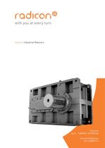
Series G Industrial Reducers Technical Up to - 1,860kW / 165,000 Nm Industrial Reducers CG-2.00GB1211
Open the catalog to page 1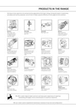
PRODUCTS IN THE RANGE Serving an entire spectrum of mechanical drive applications from food, energy, mining and metal; to automotive, aerospace and marine propulsion, we are here to make a positive difference to the supply of drive solutions. Series A Worm Gear units and geared motors in single & double reduction types Series BD Screwjack worm gear unit Series BS Worm gear unit Series C Right angle drive helical worm geared motors & reducers Series F Parallel angle helical bevel helical geared motors & reducers Series G Helical parallel shaft & bevel helical right angle drive gear units Series...
Open the catalog to page 2
ATEX Compliance Assured Total compliance with the ATEX Directive safeguarding the use of industrial equipment in potentially explosive atmospheres is assured for users of our geared products. Certification is available for standard gearboxes and geared motors with badging displaying the CE Mark and the Ex mark, name and location of the manufacturer, designation of series or type, serial number, year of manufacture, Ex symbol and equipment group/category. ATEX directive 94/9/EC (also known as ATEX 95 or ATEX 100A) and the CE Marking Directive are enforced in all EC member states. Compliance is...
Open the catalog to page 3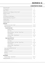
SERIES G CONTENTS PAGE General Description 1 Unit Designations 2 Design Features 3-4 Explanation and use of Ratings and Service Factors 5-7 Selection Procedure 8-9 Lubrication 10 Unit Handings and Shaft Rotations Standard Shaft Sealing Arrangements 13 Inputshaft Options 14 Outputshaft Options 15 Outputbore Options 16 11 - 12 REDUCER Overhung & Axial Loads on Shafts 19 - 20 Agitator Applications 21 - 22 Parallel Shaft Units Moments of Inertia 25 Exact Ratios 26 Mechanical Ratings - Input Power / Output Torque 27 - 31 Thermal Ratings 32 Dimension Sheets - Speed Reducers 33 - 36 Fan Cooling 37 Right...
Open the catalog to page 5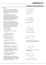
SERIES G GENERAL DESCRIPTION Series G Series G gear units are available in parallel shaft helical units and right angle shaft bevel/helical units in double, triple and quadruple reduction gear stages having a maximum output torque of up to 162,000 Nm. Parallel shaft unit The modular design and construction of the Series G offers many engineering and performance benefits including a high degree of interchangeability of parts and sub assemblies. This in turn provides considerable economies of production whilst maintaining the highest standard of component integrity. Adding to the range of power...
Open the catalog to page 6
SERIES G UNIT DESIGNATIONS 1 2 3 4 5 6 7 8 9 10 11 12 13 14 15 16 17 18 19 20 * THIS PAGE MAY BE PHOTOCOPIED ALLOWING THE CUSTOMER TO ENTER THEIR ORDER * EXAMPLE G 1 4 3 0 5 0 . H - - - - R L 1 - - - 20 - TORQUE ARM & Gearcase Finish 1 - SERIES G RANGE G - - 1 4 THROUGH 2 2 - TORQUE ARM + STD PAINT C 2, 3 - SIZE OF UNIT NO TORQUE ARM + STD PAINT T - STD EXTREME CLIMATIC PAINT F - STD EXTREME CLIMATIC PAINT + TORQUE ARM Z - SPECIAL 4 - O OF REDUCTIONS N 2 THROUGH 4 19 - CASE CONSTRUCTION - S - SG IRON F - FABRICATED STEEL CASE 5 - REVISION VERSION 0 - CAST IRON ETC 18 - OIL LEVEL - - DIPSTICK...
Open the catalog to page 7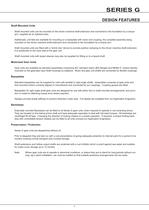
SERIES G DESIGN FEATURES Shaft Mounted Units Shaft mounted units can be mounted on the driven machine shaft extension and connected to the foundation by a torque arm, supplied as an optional extra. Additionally, unit feet are available for mounting on a baseplate with motor and coupling, the complete assembly being mounted on the driven machine shaft extension and connected to the foundation by a torque arm. Shaft mounted units are fitted with a 'shrink disc' device to provide positive clamping on the driven machine shaft extension. It is positioned on the input side of the gear unit. Shaft mounted...
Open the catalog to page 8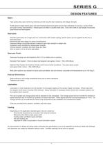
SERIES G DESIGN FEATURES Gears High quality alloy case hardening materials provide long life wear resistance and fatigue strength. Profile ground single helical gears and hard finished spiral bevel gears ensure high standards of accuracy, surface finish and quiet running characteristics. Helical gears are fitted in parallel shaft units. Units with shafts at right angles incorporate spiral bevel and helical gears. Gearcases Standard gearcases are of rigid cast iron construction with modern styling, special cases can be supplied as SG iron or fabricated steel. Horizontal split case design for ease...
Open the catalog to page 9
SERIES G EXPLANATION AND USE OF RATINGS AND ASSOCIATED RATING FACTORS Gear unit selection is made by comparing actual loads with catalogue ratings. Catalogue ratings are based on a standard set of loading conditions, whereas actual load conditions vary according to type of application. Service Factors are therefore used to calculate an equivalent load to compare with catalogue ratings. i.e. Equivalent Load = Actual Load x Service Factor Mechanical and Thermal Service Factor must be considered:- Mechanical Service Factors Fm and Fs Thermal Service Factors Ft, Fd, Fh and Fv Mechanical ratings and...
Open the catalog to page 10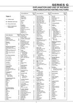
SERIES G EXPLANATION AND USE OF RATINGS AND ASSOCIATED RATING FACTORS Driven Machine Table 3 U = Uniform load M = Moderate shock load H = Heavy shock load = Refer to Application Engineering type of load Cranes main hoists bridge travel trolley travel Crusher ore H stone H sugar H Dredges cable reels M conveyors M cutter head drives H jig drives H manoeuvring winches M pumps M screen drive H stackers M utility winches M type of Dry dock cranes load main hoist auxiliary hoist boom, luffing Agitators rotating, swing or slew pure liquids U tracking, drive wheels liquids and solids M liquids-variable...
Open the catalog to page 11
SERIES G EXPLANATION AND USE OF RATINGS AND ASSOCIATED RATING FACTORS Thermal ratings and service factors The Thermal ratings are a measure of the gear units ability to dissipate heat. If they are exceeded the lubricant may overheat and breakdown, resulting in gear failure. Thermal ratings are given on page 32 for parallel shaft units and page 46 for right angle shaft units. The following choices are available: i) No additional cooling ii) Unit fitted with fan cooling iii) Unit fitted with water cooling coil iv) Unit fitted with cooling coil and fan Catalogue thermal limitations are based on...
Open the catalog to page 12All Radicon catalogs and technical brochures
 Series M Helical In-Line
116 Pages
 BR-Series-AM.
72 Pages
 adicon-SeriesX
32 Pages
 BR Series F
117 Pages
 Radicon Series X Couplings
32 Pages
 BR Series X Couplings
36 Pages
 BR Cone Ring Couplings
16 Pages
 Series J
73 Pages
 Motor
Motor4 Pages
 Series E Flyer
4 Pages
 G series
4 Pages
 BD
BD4 Pages
 Product Brochure radicon
8 Pages
 Benzlers Screw Jacks
69 Pages
 Series J - Shaft Mounted Gearbox
15 Pages
 Radicon Series ET
42 Pages
 BR Series G
71 Pages
 Metric
8 Pages
 Geared Pump
15 Pages
 Series P Planetary
4 Pages
 M series
120 Pages
 Sala Gears
74 Pages
 Screw Jacks
58 Pages
 Roloid Pump
17 Pages
 Heavy Duty Worm Gear Series ER
15 Pages
 C series
120 Pages
 F series
119 Pages
 Series AM Worm Gear
73 Pages
 Worm Gear Series AJ
89 Pages
 Series BS Worm Gear
60 Pages
 Elflex Flexible Couplings
8 Pages
 Series H industrial gearboxes
123 Pages
 Geared Motor Series K
90 Pages
 Elign Gear Couplings
17 Pages


Archived catalogs
 Worm Gears Series AH
13 Pages


- Industrial pump
- Pump with electric motor
- Stationary pump
- Seawater pump
- Electric gearmotor
- Planetary gearbox
- Coaxial gearhead
- Food product pump
- Right angle gearhead
- Direct current gear-motor
- Compact gearhead
- Solid-shaft gearhead
- Hollow-shaft gearhead
- Flexible coupling
- Gearbox for industrial applications
- Transmission gearhead
- Industrial electric gearmotor
- Coaxial gearmotor
- Shaft gearhead