Sala Gears

Sala Gears
Catalog excerpts

Series J Shaft Mounted Gearbox Technical Up to - 600kW / 57,000 Nm Industrial Gearbox CJ-2.00GB1211
Open the catalog to page 1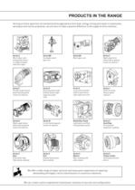
Serving an entire spectrum of mechanical drive applications from food, energy, mining and metal; to automotive, aerospace and marine propulsion, we are here to make a positive difference to the supply of drive solutions. Worm Gear units reduction types Parallel angle helical bevel helical geared motors & reducers Right angle helical bevel helical geared motors & reducers Screwjack worm gear unit Helical parallel shaft & bevel helical right angle drive gear In-line helical geared motors & reducers Worm gear unit Large helical parallel shaft & bevel helical right angle drive units Roloid Gear Pump...
Open the catalog to page 2
ATEX Compliance Assured Total compliance with the ATEX Directive safeguarding the use of industrial equipment in potentially explosive atmospheres is assured for users of our geared products. Certification is available for standard gearboxes and geared motors with badging displaying the CE Mark and the Ex mark, name and location of the manufacturer, designation of series or type, serial number, year of manufacture, Ex symbol and equipment group/category. ATEX directive 94/9/EC (also known as ATEX 95 or ATEX 100A) and the CE Marking Directive are enforced in all EC member states. Compliance is...
Open the catalog to page 3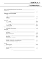
SERIES J CONTENTS PAGE Series J Shaftmounted Speed Reducers, General Description _________________________________ 4 Unit Designations ____________________________________________________________________ 5 Selection Procedure __________________________________________________________________ 6-7 Power ratings / Thermal power ratings 1-stage _______________________________________________________________________ 8 2-stage 15:1 ___________________________________________________________________ 9 - 10 2-stage 20:1 ___________________________________________________________________ 11 2-stage 25:1...
Open the catalog to page 5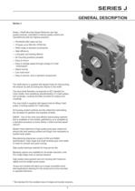
SERIES J GENERAL DESCRIPTION Series J Series J Shaft Mounted Speed Reducers are high quality products, submitted to intense quality control and manufactured with the highest precision. — Worldwide after sales service — 19 types up to 600 kW, 57000 Nm — Wide range of standard accessories — High efficiency — Long gear and bearing lifetime — All mounting positions possible — Easy to mount — Easy to change speed through change of V-belt transmission — Space saving — Low noise level — Easy to service, due to standard components The shaft sleeve is supplied with tapped holes for dismounting the reducer...
Open the catalog to page 6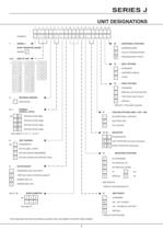
UNIT DESIGNATIONS SHAFT MOUNTED GEARS nitial Version OVERALL RATIO eg | - || 5 | Standard single stage | 1 || 5 | Standard double stage | 2 || 0 | Standard double stage | 2 || 5 | Standard double stage |T~| STDRL (BALL JOINT) - STANDARD HOLLOW SHAFT - Kl BO See Hollow shaft bores page 54 BORE DIAMETER ADDITIONAL FEATURES PULLEY OR/AND MOTOR SEAL OPTIONS LABYRINTH SEALS SPECIAL COLOUR (ALKYD)* TWO PACK HIGH SOLID SPECIFY TYPE AND COLOUR COOLING OPTIONS (ONLY J100 - 190) | B || V | LEFT ROTATION (Counter-Clockwise) | B || H | RIGHT ROTATION (Clockwise) MOUNTING POSITIONS SPECIFY MOTOR SIZE •THIS...
Open the catalog to page 7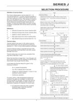
SELECTION PROCEDURE Definition of service factor The torque ratings apply to service factor fb = 1,0. The service factor fb = 1,0 gives continual operation 4 to 8 hours a day at a uniform load without shocks and with 10 to 200 starts an hour. The moment of inertia of the driven machines is less than 20 % of the electric motor inertia and occasional peak torque may not exceed 1,8 times the torque rating. For other running conditions compensate with service factors according Pe = Demand of power from driven machine (kW) T = Demand of torque from driven machine (Nm) ne = Speed on driven machine...
Open the catalog to page 8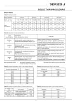
SELECTION PROCEDURE Service factors Table 1. Service factor fb Table 2. Description of load classifications Mass acceleration factor all external moments of inertia ' calculated with reference to the motor speed moment of inertia of driving motor Table 3. Ambient temperature factor ft (All cooling methods) Table 4. Altitude factor fa (Only for air cooling) Table 5. Ambient air velocity factor fv (Without electric fan) Table 6. Operation time factor fu (All cooling methods)
Open the catalog to page 9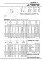
POWER RATINGS - SINGLE REDUCTION Specification of factor for V-belt forces in different angles. Power ratings have to be multiplied with this factor for sizes J100 - 190 when motor is located in angle 90-210 °. Single reduction The torque is shown in Nm (1 Nm = 0.102 kpm = 0.7376 Ibf.ft) Thermal rating Pt kW at 25 C ambient temperature outdoor at continuous When the reducer is working with a low output speed less than: Please contact our Application Engineers
Open the catalog to page 10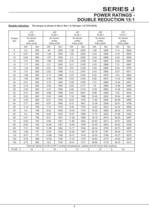
POWER RATINGS - Double reduction The torque is shown in Nm (1 Nm = 0.102 kpm = 0.7376 Ibf.ft)
Open the catalog to page 11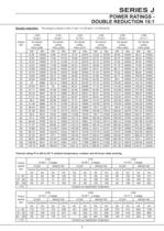
POWER RATINGS - Double reduction The torque is shown in Nm (1 Nm = 0.102 kpm = 0.7376 Ibf.ft) Thermal rating Pt in kW at 25° C ambient temperature, outdoor and 24 hours daily working.
Open the catalog to page 12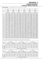
POWER RATINGS - Double reduction The torque is shown in Nm (1 Nm = 0.102 kpm = 0.7376 Ibf.ft) Thermal rating Pt in kW at 25° C ambient temperature, outdoor and 24 hours daily working.
Open the catalog to page 13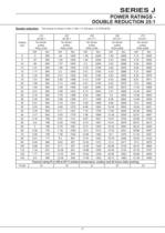
POWER RATINGS - Double reduction The torque is shown in Nm (1 Nm = 0.102 kpm = 0.7376 Ibf.ft)
Open the catalog to page 14
POWER RATINGS - Double reduction The torque is shown in Nm (1 Nm = 0.102 kpm = 0.7376 Ibf.ft) Thermal rating Pt in kW at 25° C ambient temperature, outdoor and 24 hours daily working.
Open the catalog to page 15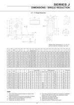
DIMENSIONS - SINGLE REDUCTION Please note: Dimensions R, T, T1, T2, T3 are not machined, deviations can occur. 1. The V-belt pulley should be placed as close to the 2. These dimensions are minimum diameters of driven pulley to prevent overloading of the bearings. 5. The reducer should normally be mounted on a shaftwith tolerance ISOjs6. On heavy duty applications closer 8. Space for spacer if locking ring is used.
Open the catalog to page 16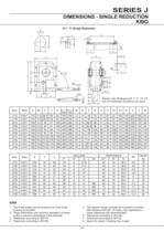
DIMENSIONS - SINGLE REDUCTION 1. The V-belt pulley should be placed as close to the 2. These dimensions are minimum diameters of driven pulley to prevent overloading of the bearings. 5. The reducer should normally be mounted on a shaft with tolerance ISO js6. On heavy duty applications closer tolerances are recommended. 8. Space for spacer if locking ring is used.
Open the catalog to page 17All Radicon catalogs and technical brochures
 Series M Helical In-Line
116 Pages
 BR-Series-AM.
72 Pages
 adicon-SeriesX
32 Pages
 BR Series F
117 Pages
 Radicon Series X Couplings
32 Pages
 BR Series X Couplings
36 Pages
 BR Cone Ring Couplings
16 Pages
 Series J
73 Pages
 Motor
Motor4 Pages
 Series E Flyer
4 Pages
 G series
4 Pages
 BD
BD4 Pages
 Product Brochure radicon
8 Pages
 Benzlers Screw Jacks
69 Pages
 Series J - Shaft Mounted Gearbox
15 Pages
 Radicon Series ET
42 Pages
 BR Series G
71 Pages
 Metric
8 Pages
 Geared Pump
15 Pages
 Series P Planetary
4 Pages
 M series
120 Pages
 Screw Jacks
58 Pages
 Roloid Pump
17 Pages
 Heavy Duty Worm Gear Series ER
15 Pages
 SERIE G
71 Pages
 C series
120 Pages
 F series
119 Pages
 Series AM Worm Gear
73 Pages
 Worm Gear Series AJ
89 Pages
 Series BS Worm Gear
60 Pages
 Elflex Flexible Couplings
8 Pages
 Series H industrial gearboxes
123 Pages
 Geared Motor Series K
90 Pages
 Elign Gear Couplings
17 Pages


Archived catalogs
 Worm Gears Series AH
13 Pages


- Industrial pump
- Pump with electric motor
- Stationary pump
- Seawater pump
- Electric gearmotor
- Planetary gearbox
- Coaxial gearhead
- Food product pump
- Direct current gear-motor
- Right angle gearhead
- Compact gearhead
- Solid-shaft gearhead
- Flexible coupling
- Hollow-shaft gearhead
- Gearbox for industrial applications
- Transmission gearhead
- Industrial electric gearmotor
- Shaft gearhead
- Coaxial gearmotor