Catalog excerpts
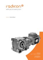
Engineered around you www.davidbrown.com Series X Couplings Couplings CX-1.00GBD1209
Open the catalog to page 1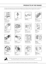
SERIES X PRODUCTS IN THE RANGE Serving an entire spectrum of mechanical drive applications from food, energy, mining and mtal; to automotive, aerospace and marine propulsion, we are here to make a positive diffrence to the supply ofdrive solutions. S驩ries A Sries B Sries BD HTP S驩ries BS Sries C WormGearunits Conexhelicoidal Screwjackworm Hightorque Wormgearunit Rightangledrive and geared motors gear geometry right gear unit planetary gear units helical worm geared in single & double angle gearmotors motors & reducers rduction types and reducers DuoDrive S驩ries E Extruder Drive Sries...
Open the catalog to page 2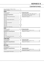
SERIES X CONTENTS PAGE General Information / Reference Notes 4 Selection Procedure 5 - 7 GEAR General Description 10 - 11 Unit Designations 12 Dimensions & Specifications Type GCO2 13 Type GC05 Floating Shaft Assembly 14 Type G20 15 Type G52 16 Type G52 Floating Shaft Assembly 17 - 18 Type G32 19 Type G82 20 G Mill Motor & Taper Bores 21 Type GF20 22 Type GF52 23 - 25 Type GF32 26 GF Mill Motor & Taper Bores 27 Engineering Data Recommended Keys for Shaft - Metric and Inch 28 Motor Shafts and Ratings - Metric and Inch 28 Recommended Bore Tolerances 29 Misalignment Capacities 28 GRID General...
Open the catalog to page 3
SERIES X GENERAL INFORMATION REFERENCE NOTES 4
Open the catalog to page 7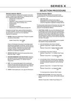
SERIES X SELECTION PROCEDURE 5
Open the catalog to page 8
SERIES X SELECTION PROCEDURE 6
Open the catalog to page 9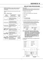
SERIES X SELECTION PROCEDURE 7
Open the catalog to page 10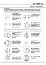
SERIES X GEAR COUPLINGS 10
Open the catalog to page 13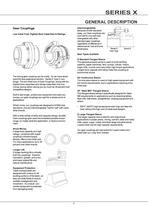
SERIES X GENERAL DESCRIPTION 11
Open the catalog to page 14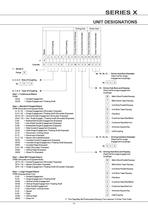
SERIES X UNIT DESIGNATIONS 12
Open the catalog to page 15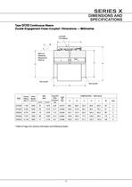
SERIES X DIMENSIONS AND SPECIFICATIONS 13
Open the catalog to page 16
SERIES X DIMENSIONS AND SPECIFICATIONS 14
Open the catalog to page 17
SERIES X DIMENSIONS AND SPECIFICATIONS 15
Open the catalog to page 18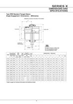
SERIES X DIMENSIONS AND SPECIFICATIONS 16
Open the catalog to page 19
SERIES X DIMENSIONS AND SPECIFICATIONS 17
Open the catalog to page 20
SERIES X DIMENSIONS AND SPECIFICATIONS 18
Open the catalog to page 21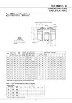
SERIES X DIMENSIONS AND SPECIFICATIONS 19
Open the catalog to page 22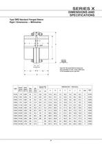
SERIES X DIMENSIONS AND SPECIFICATIONS 20
Open the catalog to page 23
SERIES X DIMENSIONS AND SPECIFICATIONS 21
Open the catalog to page 24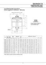
SERIES X DIMENSIONS AND SPECIFICATIONS 22
Open the catalog to page 25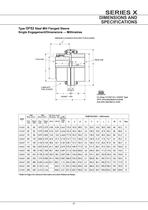
SERIES X DIMENSIONS AND SPECIFICATIONS 23
Open the catalog to page 26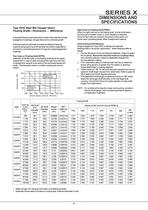
SERIES X DIMENSIONS AND SPECIFICATIONS 24
Open the catalog to page 27
SERIES X DIMENSIONS AND SPECIFICATIONS 25
Open the catalog to page 28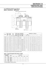
SERIES X DIMENSIONS AND SPECIFICATIONS 26
Open the catalog to page 29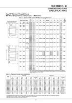
SERIES X DIMENSIONS AND SPECIFICATIONS 27
Open the catalog to page 30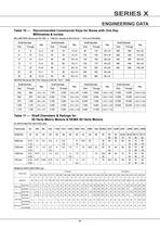
SERIES X ENGINEERING DATA 28
Open the catalog to page 31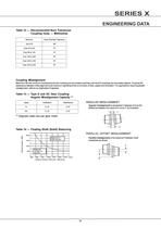
SERIES X ENGINEERING DATA 29
Open the catalog to page 32
SERIES X GRID TYPE COUPLINGS 32
Open the catalog to page 35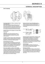
SERIES X GENERAL DESCRIPTION 33
Open the catalog to page 36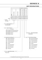
SERIES X UNIT DESIGNATIONS 34
Open the catalog to page 37
SERIES X DIMENSIONS AND SPECIFICATIONS 35
Open the catalog to page 38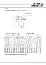
SERIES X DIMENSIONS AND SPECIFICATIONS 36
Open the catalog to page 39
SERIES X DIMENSIONS AND SPECIFICATIONS 37
Open the catalog to page 40
SERIES X DIMENSIONS AND SPECIFICATIONS 38
Open the catalog to page 41
SERIES X DIMENSIONS AND SPECIFICATIONS 39
Open the catalog to page 42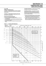
SERIES X DIMENSIONS AND SPECIFICATIONS 40
Open the catalog to page 43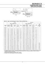
SERIES X DIMENSIONS AND SPECIFICATIONS 41
Open the catalog to page 44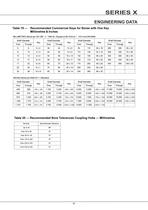
SERIES X ENGINEERING DATA 42
Open the catalog to page 45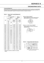
SERIES X ENGINEERING DATA 43
Open the catalog to page 46
SERIES X GENERAL DESCRIPTION 46
Open the catalog to page 49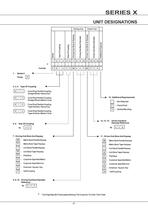
SERIES X UNIT DESIGNATIONS 47
Open the catalog to page 50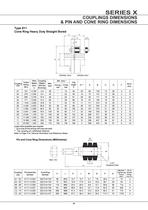
SERIES X COUPLINGS DIMENSIONS & PIN AND CONE RING DIMENSIONS E E C D G** F B A M J øK øL øP N H 48
Open the catalog to page 51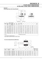
SERIES X COUPLINGS DIMENSIONS & PIN AND CONE RING DIMENSIONS E E C D G** F B A T T Not available as taper bushed M J øK øL øP N H 49
Open the catalog to page 52
SERIES X ENGINEERING DATA 50
Open the catalog to page 53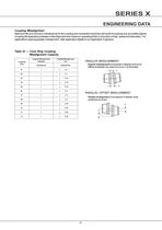
SERIES X ENGINEERING DATA 51
Open the catalog to page 54
SERIES X GENERAL DESCRIPTION 54
Open the catalog to page 57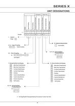
SERIES X UNIT DESIGNATIONS 55
Open the catalog to page 58
SERIES X DIMENSIONS AND SPECIFICATIONS A D E F E B C 56
Open the catalog to page 59
SERIES X ENGINEERING DATA 57
Open the catalog to page 60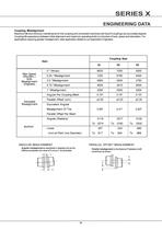
SERIES X ENGINEERING DATA Backlash 58
Open the catalog to page 61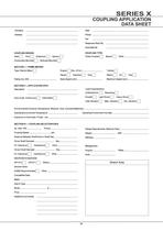
SERIES X COUPLING APPLICATION DATA SHEET 59
Open the catalog to page 62
SERIES X Contacts AUSTRALIA David Brown Gear Industries Ltd 13-19 Franklin Avenue Bulli, NSW2516 Australia Tel: +61 2 4283 0300 Fax: +61 2 4283 0333 EUROPE Benzler TBA BV Jachthavenweg 2 NL-5928 NTVenlo Netherlands & the rest of Europe Tel: +31 77 324 59 00 Fax: +31 77 324 59 01 Austria Tel: +43 7 229 618 91 Fax: +43 7 229 618 84 Germany Tel: 0800 350 40 00 Fax: 0800 350 40 01 ITALY David Brown Hydraulics Italia S.R.L. Via Del Costruttore, 64 41058-Vignola (MO) Italy Tel: +39 059 770 0411 Fax: +39 059 770 0425 THAILAND David Brown (Thailand) Ltd 700/43 Moo 6 Amata Nakorn Industrial Estate...
Open the catalog to page 63
Single Extended Double Extended Outputshaft Outputshaft See Page 82 See Page 82 Shrink Disc Torque Bracket See Page 85 See Page 88 B5 (D) Flange Mounting B14 (C) Flange Mounting See Page 89 See Page 90 > 62 size="-1">
Open the catalog to page 65
o C to + 50 > o C When a backstop module is fitted dimension K1 should be added to the overall length of the geared motor assembly. > K1 6g Removal of motor or backstop will release the drive. Ensure all driven machinery is secure prior to any maintenance work > Motor Frame Size Lift off Speed (n葒 min) (rev/min) Rated Locking Torque (T maxђ) (at motor) (Nm) g6 K1100 67017025070 112 67017025070 132 62094030095 160 620940350130 180 620940350130 200 5501260400130 > Motor Frame Size Lift off Speed (n葒 min) (rev/min) Rated Locking Torque (T maxђ) (at motor) (Nm) g6 K1182TC / 184TC 67030022895.25...
Open the catalog to page 66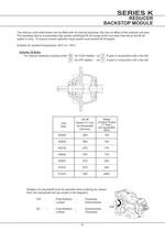
o C to + 50 > o C RatedLocking Torque (T maxђ) (at inputshaft) (Nm)Lift off Speed (nђ min)(at inputshaft) (rev/min) For reducer backstop modules enter W for CCW rotation (or Z if used in conjunction with a fan kit) X for CW rotation (or Y if used in conjunction with a fan kit) Column 10 Entry UnitSize K0532 800 100 K0632 800 100 K0732 670 170 K0832 670 170 K0931 670 300 K1031 670 300 K1231 550 2400 Rotation of outputshaft must be specified when ordering as viewed from the outputshaft end (as shown in the diagram) CW - Free Rotation - Clockwise Locked - Anticlockwise AC - Free Rotation -...
Open the catalog to page 83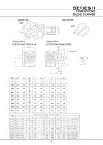
Sizes K09 to K12 Sizes K03 to K08 > 8 Holess1 dia4 Holess1 dia Tapped HolevOutput Shaft e1 e1 Mo Mo
Open the catalog to page 87All Radicon catalogs and technical brochures
-
Series M Helical In-Line
116 Pages
-
BR-Series-AM.
72 Pages
-
adicon-SeriesX
32 Pages
-
BR Series F
117 Pages
-
Radicon Series X Couplings
32 Pages
-
BR Series X Couplings
36 Pages
-
BR Cone Ring Couplings
16 Pages
-
Series J
73 Pages
-
Motor
4 Pages
-
Series E Flyer
4 Pages
-
G series
4 Pages
-
BD
4 Pages
-
Product Brochure radicon
8 Pages
-
Benzlers Screw Jacks
69 Pages
-
Series J - Shaft Mounted Gearbox
15 Pages
-
Radicon Series ET
42 Pages
-
BR Series G
71 Pages
-
Metric
8 Pages
-
Geared Pump
15 Pages
-
Series P Planetary
4 Pages
-
M series
120 Pages
-
Sala Gears
74 Pages
-
Roloid Pump
17 Pages
-
Heavy Duty Worm Gear Series ER
15 Pages
-
Screw Jacks
58 Pages
-
Series AM Worm Gear
73 Pages
-
Worm Gear Series AJ
89 Pages
-
Series BS Worm Gear
60 Pages
-
Elflex Flexible Couplings
8 Pages
-
Series H industrial gearboxes
123 Pages
-
SERIE G
71 Pages
-
C series
120 Pages
-
F series
119 Pages
-
Elign Gear Couplings
17 Pages
Archived catalogs
-
Worm Gears Series AH
13 Pages


