Catalog excerpts

with you at every turn ELign Gear Couplings
Open the catalog to page 1
Serving an entire spectrum of mechanical drive applications from food, energy, mining and metal; to automotive, aerospace and marine propulsion, we are here to make a positive difference to the supply of drive solutions. Worm Gear units reduction types Parallel angle helical bevel helical geared motors & reducers Right angle helical bevel helical geared motors & reducers Screwjack worm gear unit Helical parallel shaft & bevel helical right angle drive gear In-line helical geared motors & reducers Worm gear unit Large helical parallel shaft & bevel helical right angle drive units Roloid Gear...
Open the catalog to page 2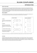
ELIGN COUPLINGS GEAR COUPLINGS A Gear Coupling is used to join two rotating shafts for efficient transmission of mechanical power. Although the shafts are ac- curately aligned at the time of installation, it is likely that during the operation the alignment may get disturbed due to setting of foundation, thermal expansion, shaft deflection, wearing out of other parts, improper maintenance and many more reasons. Due to this unavoidable misalignment occurring during the operation a gear coupling provides a better solution to compensate or minimise the effect of misalignment. The gear...
Open the catalog to page 3
ELIGN COUPLINGS FEATURES OF ELIGN COUPLINGS ELIGN Gear coupling consists of hubs with multi crowned teeth at Flank, tip and chamfering on teeth. Crowned Flanks: The flanks of the teeth are crowned so that the tooth thickness is greatest at that centre of the tooth. This ensures a larger con- tact area per tooth for higher torque requirements and puts more teeth in contact for the given angle. Actual tooth loading takes place near the centre of the tooth face where tooth thickness is greatest, Crowned flanks also eliminate end-of-tooth loading, provide optimal load distribution, and...
Open the catalog to page 4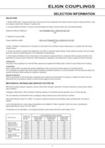
ELIGN COUPLINGS SELECTION INFORMATION 1. Obtain Shaft Sizes, compare shaft sizes of driving and driven equipment with listed maximum bores of desired series or type of coupling to determine "tentative" coupling size. 2. Compute effective kW/rpm or torque to be transmitted and select a service factor from the following tables. Determine kW/rpm (effective) = kW TRANSMITTED X SERVICE FACTOR or determine Torque daNm Torque (effective) daNm = 955 X kW TRANSMITTED X SERVICE FACTOR Confirm "Tentative" Coupling size or increase to a size which has a kW/rpm torque rating equal to or greater than the...
Open the catalog to page 5
ELIGN COUPLINGS SELECTION INFORMATION 1. Obtain Shaft Sizes, compare shaft sizes of driving and driven equipment with listed maximum bores of desired series or type of coupling to determine "tentative" coupling size. 2. Compute effective kW/rpm or torque to be transmitted and select a service factor from the following tables. Determine kW/rpm (effective) = kW TRANSMITTED X SERVICE FACTOR or determine Torque daNm Torque (effective) daNm = 955 X kW TRANSMITTED X SERVICE FACTOR Confirm "Tentative" Coupling size or increase to a size which has a kW/rpm torque rating equal to or greater than the...
Open the catalog to page 6
ELIGN COUPLINGS SERVICE FACTORS Driven Machine Table 2 U = Uniform load M = Moderate shock load H = Heavy shock load = Refer to Application Engineering type of load Driven Machine type of load log haul-incline H log haul-well type H log turning device H main log conveyor H off bearing rolls M planer feed chains M planer floor chains M M planer tilting hoist re-saw merry-go-round conveyor M roll cases H H slab conveyor small waste conveyor-belt U small waste conveyor-chain M sorting table M tipple hoist conveyor M tipple hoist drive M transfer conveyors M transfer rolls M M tray drive...
Open the catalog to page 7
ELIGN COUPLINGS Multi Crowned Toothed Couplings For Shaft Connections Type ED 1 SPACE REQUIRED TO CHANGE THE SEAL 3 MAXIMUM ANGULAR MISALIGNMENT PER COUPLING HALF 0.75 4 WEIGHT & MOMENT OF INERTIA BASED ON PILOT BORE CONDITION. 5 CONTINUOUS TORQUE RATING SUBJECT TO ACCURATE ALIGNMENT OF CONNECTING SHAFTS. 6 FOR AHIGHER SIZE REQUIREMENT, PLEASE CONTACT APPLICATION ENGINEERING. In accordance with our established policy to constantly improve our products, these specifications are subject to change with-
Open the catalog to page 8
ELIGN COUPLINGS _TYPE ED (SUPER SERIES) Multi Crowned Toothed Couplings For Shaft Connections Type ED (SUPER SERIES) 1. SPACE REQUIRED TO CHANGE THE SEAL 3. MAXIMUM ANGULAR MISALIGNMENT PER COUPLING HALF 0.75 4. WEIGHT & MOMENT OF INERTIA BASED ON PILOT BORE CONDITION. 5. CONTINUOUS TORQUE RATING SUBJECT TO ACCURATE ALIGNMENT OF CONNECTING SHAFTS. 6. FOR AHIGHER SIZE REQUIREMENT, PLEASE CONTACT APPLICATION ENGINEERING. 7. FOR MARKED DIMENSIONS, PLEASE CONTACT APPLICATION ENGINEERING. In accordance with our established policy to constantly improve our products, these specifications are...
Open the catalog to page 9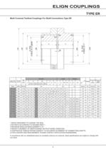
ELIGN COUPLINGS Multi Crowned Toothed Couplings For Shaft Connections Type ER 1 SPACE REQUIRED TO CHANGE THE SEAL 3 MAXIMUM ANGULAR MISALIGNMENT 0.75 4 WEIGHT & MOMENT OF INERTIA BASED ON PILOT BORE CONDITION. 5 CONTINUOUS TORQUE RATING SUBJECT TO ACCURATE ALIGNMENT OF CONNECTING SHAFTS. 6 FOR AHIGHER SIZE REQUIREMENT, PLEASE CONTACT APPLICATION ENGINEERING. In accordance with our established policy to constantly improve our products, these specifications are subject to change with-
Open the catalog to page 10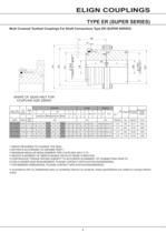
ELIGN COUPLINGS _TYPE ER (SUPER SERIES) Multi Crowned Toothed Couplings For Shaft Connections Type ER (SUPER SERIES) SHAPE OF GEAR HALF FOR 1 SPACE REQUIRED TO CHANGE THE SEAL 3 MAXIMUM ANGULAR MISALIGNMENT PER COUPLING HALF 0.75 4 WEIGHT & MOMENT OF INERTIA BASED ON PILOT BORE CONDITION. 5 CONTINUOUS TORQUE RATING SUBJECT TO ACCURATE ALIGNMENT OF CONNECTING SHAFTS. 6 FOR A HIGHER SIZE REQUIREMENT, PLEASE CONTACT APPLICATION ENGINEERING. 7 FOR MARKED DIMENSIONS, PLEASE CONTACT APPLICATION ENGINEERING. In accordance with our established policy to constantly improve our products, these...
Open the catalog to page 11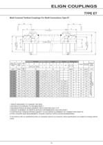
ELIGN COUPLINGS Multi Crowned Toothed Couplings For Shaft Connections Type ET 1 SPACE REQUIRED TO CHANGE THE SEAL 3 MAXIMUM ANGULAR MISALIGNMENT PER COUPLING HALF 0.75 4 WEIGHT & MOMENT OF INERTIA WITHOUT INTERMEDIATE HOLLOW SHAFT. 5 CONTINUOUS TORQUE RATING SUBJECT TO ACCURATE ALIGNMENT OF CONNECTING SHAFTS. 6 FOR AHIGHER SIZE REQUIREMENT, PLEASE CONTACT APPLICATION ENGINEERING. In accordance with our established policy to constantly improve our products, these specifications are subject to change without
Open the catalog to page 12All Radicon catalogs and technical brochures
-
Series M Helical In-Line
116 Pages
-
BR-Series-AM.
72 Pages
-
adicon-SeriesX
32 Pages
-
BR Series F
117 Pages
-
Radicon Series X Couplings
32 Pages
-
BR Series X Couplings
36 Pages
-
BR Cone Ring Couplings
16 Pages
-
Series J
73 Pages
-
Motor
4 Pages
-
Series E Flyer
4 Pages
-
G series
4 Pages
-
BD
4 Pages
-
Product Brochure radicon
8 Pages
-
Benzlers Screw Jacks
69 Pages
-
Series J - Shaft Mounted Gearbox
15 Pages
-
Radicon Series ET
42 Pages
-
BR Series G
71 Pages
-
Metric
8 Pages
-
Geared Pump
15 Pages
-
Series P Planetary
4 Pages
-
M series
120 Pages
-
Sala Gears
74 Pages
-
Roloid Pump
17 Pages
-
Heavy Duty Worm Gear Series ER
15 Pages
-
Screw Jacks
58 Pages
-
Series AM Worm Gear
73 Pages
-
Worm Gear Series AJ
89 Pages
-
Series BS Worm Gear
60 Pages
-
Elflex Flexible Couplings
8 Pages
-
Series H industrial gearboxes
123 Pages
-
SERIE G
71 Pages
-
C series
120 Pages
-
Geared Motor Series K
90 Pages
-
F series
119 Pages
Archived catalogs
-
Worm Gears Series AH
13 Pages


