C series

C series
Catalog excerpts

Series C Helical Worm Technical Up to - 45kW / 10,000 Nm Geared Motors CC-2.00GB1211
Open the catalog to page 1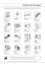
PRODUCTS IN THE RANGE Serving an entire spectrum of mechanical drive applications from food, energy, mining and metal; to automotive, aerospace and marine propulsion, we are here to make a positive difference to the supply of drive solutions. Series A Worm Gear units and geared motors in single & double reduction types Series BD Screwjack worm gear unit Series BS Worm gear unit Series C Right angle drive helical worm geared motors & reducers Series F Parallel angle helical bevel helical geared motors & reducers Series G Helical parallel shaft & bevel helical right angle drive gear units Series...
Open the catalog to page 2
ATEX Compliance Assured Total compliance with the ATEX Directive safeguarding the use of industrial equipment in potentially explosive atmospheres is assured for users of our geared products. Certification is available for standard gearboxes and geared motors with badging displaying the CE Mark and the Ex mark, name and location of the manufacturer, designation of series or type, serial number, year of manufacture, Ex symbol and equipment group/category. ATEX directive 94/9/EC (also known as ATEX 95 or ATEX 100A) and the CE Marking Directive are enforced in all EC member states. Compliance is...
Open the catalog to page 3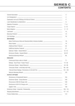
SERIES C CONTENTS General Description 3 Unit Designations 4 Explanation and use of Ratings and Service Factors 5 Load Classification by Applications 6 Selection Procedure 7-8 Output Options 9 - 10 Motor Adaptors 11 - 13 Lubrication 14 Mounting Positions 15 Unit Handings 16 MOTORISED Motor Performance Data and Standard Motor Variants Available 18 Motor Details 19 Additional Motor Features 20 Additional Gearbox Features 21 Selection Tables - Geared Motors 22 - 61 Dimension Sheets - Geared Motors 62 -67 Motorised Backstop Module 69 REDUCER Overhung & Axial Loads on Shafts 71 Ratings - Input Power...
Open the catalog to page 5
SERIES C GENERAL DESCRIPTION Series C right angle helical worm geared motors and reducers provide a highly efficient and compact solution to meet most requirements up to 45 kW with maximum output torque capacity of 10,000Nm. Following a long line of power transmission products, this product adds to the growing family of new drives which has taken advantage of our many years of accumulated design expertise, together with the use of high quality materials and components. The end result is a series of speed reducing and geared motors offering high load carrying capacity, increased efficiency, quiet...
Open the catalog to page 6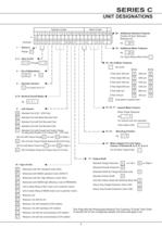
SERIES C UNIT DESIGNATIONS Gearbox Codes 1 * Motor Codes 2 3 4 5 6 7 8 9 10 11 12 13 14 15 16 17 18 19 20 0 3 2 1 5 0 . B C Example C M C - 1 D . 1 8 A - - eg 1 - Series C Range 20 - Additional Gearbox Features Double Oil Seal, Motorised Backstop Etc - F 19 - Additional Motor Features C eg - A For Types Without Motor Enter - 2, 3 - Size of Unit 0 3 Through 1 0 18 - No of Motor Features - No motor 4 - No of Reductions 50 Hz 60 Hz 3 & 4 Pole (Std) 1500 rpm eg. 1800 rpm L C 1200 rpm D M 1200 rpm N E 3600 rpm F 8 Pole 750 rpm 6,7,8 - Nominal Overall Ration K 6 Pole (High)1000 rpm 1 For Sizes 03 to...
Open the catalog to page 7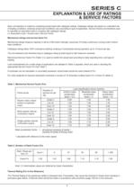
SERIES C EXPLANATION & USE OF RATINGS & SERVICE FACTORS Gear unit selection is made by comparing actual loads with catalogue ratings. Catalogue ratings are based on a standard set of loading conditions, whereas actual load conditions vary according to type of application. Service Factors are therefore used to calculate an equivalent load to compare with catalogue ratings. i.e. Equivalent Load = Actual Load x Service Factor Mechanical ratings and service factor Fm Mechanical ratings measure capacity in terms of life and/or strength, assuming 10 hr/day continuous running under uniform load conditions....
Open the catalog to page 8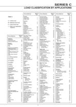
SERIES C LOAD CLASSIFICATION BY APPLICATIONS Driven Machine type of load Table 3 Cranes main hoists bridge travel trolley travel † † † U = Uniform load Crusher ore stone sugar H H H Dredges cable reels conveyors cutter head drives jig drives manoeuvring winches pumps screen drive stackers utility winches M M H H M M H M M Dry dock cranes main hoist auxiliary hoist boom, luffing rotating, swing or slew tracking, drive wheels † † † † † Elevators bucket-uniform load bucket-heavy load bucket-continuous centrifugal discharge escalators freight gravity discharge man lifts passenger U M U U U M U †...
Open the catalog to page 9
SERIES C SELECTION PROCEDURE FOR MOTORISED UNITS EXAMPLE APPLICATION DETAILS Absorbed power of driven machine = 0.7 kW Output speed of gearbox or Input speed of machine = 68 rev/min Application = Uniformly loaded belt conveyor Duration of service (hours per day) = 24hrs Mounting position = 1 Ambient temperature = 20ºC Running time (%) = 100% NOTE. If selecting a Series C Reducer Unit, a Thermal Check MUST be made in accordance with procedure on page 102 1 DETERMINE MECHANICAL SERVICE FACTOR (Fm) Refer to Load Classification by Application, table 3, page 6 Application = Uniformly loaded belt conveyor...
Open the catalog to page 10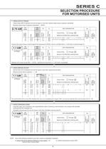
SERIES C SELECTION PROCEDURE FOR MOTORISED UNITS 4 CHECK OUTPUT TORQUE Output torque (M2) of selected unit must be equal or more than required output torque at gearbox outputshaft. Required output torque at gearbox outputshaft = 98 Nm. 74 69 64 19.12 20.61 22.11 78 84 80 1.27 1.2 1.18 UNIT DESIGNATION 1 Through 20 Spaces to be filled when entering order 2821 C 0 3 2 1 1 8 . _ M _ - _ _ . 7 5 A - - 2821 2 0 . 2821 2 2 . 19.5 Motor Frame Size Column Entry Kg Weight of Base Mount Unit N Overhung Load Fm Service Factor M2 Nm Output Torque i Ratio N2 R/MIN Output SPEED 0.75 kW 80A However the output...
Open the catalog to page 11
SERIES C OUTPUT OPTIONS OUTPUTSHAFT OPTIONS, COLUMN 11 ENTRY Column 11 Entry Standard Single Extension C on Left L11* L12 E on Right Standard Double Extension D u Std Extended Shaft for Flange Mounted Units F t Std Heavy Duty Single Extension (Size C06) J Std Heavy Duty Double Extension (Size C06) K Tapped Hole w Inch Single Extension C03 C04 P Inch Heavy Duty Single Extension (Size C06) L COLUMN 11 ENTRY ød L L11 L12 t u w Standard C, E, D 20.015 / 20.002 35 3 31 2 2.5 6 M6 x 1.0 x 16 Deep Inch N, B, P 0.7500” / 0.7495” 1.38” * 1.28” 0.83” 0.19” Standard C, E,D 25.015 / 25.002 46 3 42 28 8 Inch...
Open the catalog to page 12All Radicon catalogs and technical brochures
 Series M Helical In-Line
116 Pages
 BR-Series-AM.
72 Pages
 adicon-SeriesX
32 Pages
 BR Series F
117 Pages
 Radicon Series X Couplings
32 Pages
 BR Series X Couplings
36 Pages
 BR Cone Ring Couplings
16 Pages
 Series J
73 Pages
 Motor
Motor4 Pages
 Series E Flyer
4 Pages
 G series
4 Pages
 BD
BD4 Pages
 Product Brochure radicon
8 Pages
 Benzlers Screw Jacks
69 Pages
 Series J - Shaft Mounted Gearbox
15 Pages
 Radicon Series ET
42 Pages
 BR Series G
71 Pages
 Metric
8 Pages
 Geared Pump
15 Pages
 Series P Planetary
4 Pages
 M series
120 Pages
 Sala Gears
74 Pages
 Screw Jacks
58 Pages
 Roloid Pump
17 Pages
 Heavy Duty Worm Gear Series ER
15 Pages
 SERIE G
71 Pages
 F series
119 Pages
 Series AM Worm Gear
73 Pages
 Worm Gear Series AJ
89 Pages
 Series BS Worm Gear
60 Pages
 Elflex Flexible Couplings
8 Pages
 Series H industrial gearboxes
123 Pages
 Geared Motor Series K
90 Pages
 Elign Gear Couplings
17 Pages


Archived catalogs
 Worm Gears Series AH
13 Pages


- Industrial pump
- Pump with electric motor
- Stationary pump
- Seawater pump
- Electric gearmotor
- Planetary gearbox
- Coaxial gearhead
- Food product pump
- Direct current gear-motor
- Right angle gearhead
- Compact gearhead
- Solid-shaft gearhead
- Flexible coupling
- Hollow-shaft gearhead
- Gearbox for industrial applications
- Transmission gearhead
- Industrial electric gearmotor
- Shaft gearhead
- Coaxial gearmotor