Catalog excerpts

with you at every turn with you at every turn Series F Shaft Mounted Helical
Open the catalog to page 1
Total compliance with the ATEX Directive safeguarding the use of industrial equipment in potentially explosive atmospheres is assured for users of our geared products. Certification is available for standard gearboxes and geared motors with badging displaying the CE Mark and the Ex mark, name and location ofthe manufacturer, designation ofseries or type, serial number, year of manufacture, Ex symbol and equipment group/category. ATEX directive 94/9/EC (also known as ATEX 95 or ATEX 100A) and the CE Marking Directive are enforced in all EC member states. Compliance is compulsory for...
Open the catalog to page 2
SERIES F CONTENTS PAGE General Description _________________________________________________________________ Unit Designations Explanation and use of Ratings and Service Factors _______________________________________ Selection Procedure For Motorised Units ________________________________________________ Output Options ________________________________________________________________________ Mounting Positions Motor Performance Data __________________________________________________________ Motor Details ___________________________________________________________________ Exact Ratios...
Open the catalog to page 4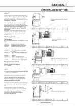
Series F Series F shaft mounted geared motors offer ratios from 5 to 100/1 in double reduction, from 100 to 360 in triple and up to 5600/1 in combined reductions. Motors are available upto 110 kW giving a maximum output torque of 16500 Nm. The series F geared motor is primarily designed as a shaft mounted unit incorporating an integral torque reaction bracket. The units are also available with rubber torque bushes, output flanges, output shafts and KIBO sleeves to allow for trouble free maintenance. All variants can be fitted with IEC motors ofyour preference orwith our standard own brand...
Open the catalog to page 5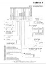
UNIT DESIGNATIONS Example 1 - Series F Range F 2,3- Size of Unit -4- Gearbox Codes |~2~| Through [T] F11 and F12in2 and 3 reductions only «___I Revision Version ◄ For Sizes 02 to 08 For Sizes 09 to 12 Standard Unit with Torque Bush T STD Unit without Torque Bush STD Unit with Output Flange Type of Unit 4- Motorised with IE2 standard motor Motorised with EPACT standard motor Motorised with IEC high efficiency motor (IE3) Motorised with NEMAhigh efficiency motor (PREMIUM) Unit to allow fitting of IEC motor (customer own motor) Unit to allow fitting of NEMA motor (customer own motor) Reducer...
Open the catalog to page 6
Gear unit selection is made by comparing actual loads with catalogue ratings. Catalogue ratings are based on a standard set of loading conditions, whereas actual load conditions vary according to type of application. Service Factors are therefore used to calculate an equivalent load to compare with catalogue ratings, i.e. Equivalent Load = Actual Load x Service Factor Mechanical ratings and service factors Fm and Fs Mechanical ratings measure capacity in termsoflife and/orstrength, assuming 10 hr/day continuous running under uniform load conditions. Catalogue ratings allow 100% overload at...
Open the catalog to page 7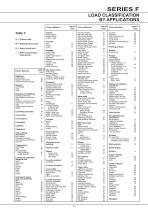
Table 3 U = Uniform load M = Moderate shock load H = Heavy shock load -j- = Refer to Application Engineering Driven Machine Agitators pure liquids U Brewing and distilling bottling machinery M brew kettles-continuous duty M mash tubs-continuous duty M scale hopper-frequent starts M Clay working machinery brick press H Conveyors-uniformly loaded or fed apron U Conveyors-heavy duty not uniformly fed apron M
Open the catalog to page 8
EXAMPLE APPLICATION DETAILS Absorbed powerof driven machine = 0.7 kW Output speed of gearbox or Input speed of machine = 63 rev/min Application = Uniformly loaded belt conveyor Duration of service (hours per day) = 24hrs 1 DETERMINE MECHANICAL SERVICE FACTOR (Fm) Referto Load Classification by Application, table 3, page 4 Application = Uniformly loaded belt conveyor loaded or fed ' U = Uniform load apron U i Referto mechanical service factor (Fm), table 1, page 3 Duration of service (hours per day) = 24hrs Selected unit’s output torque (M2) 106 Nm, therefore unit is acceptable
Open the catalog to page 9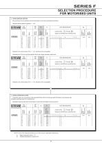
5 CHECK SERVICE FACTOR Service factor (Fm) of selected unit must be equal or more than required service factor. NOTE: If any of the following conditions occur then consult Application Engineering a) Mass acceleration factor >10 b) Ambient temperature is above 40°C
Open the catalog to page 10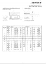
Standard / Inch Hollow Shaft Output Shaft Bore Standard Hollow Shaft | H | Standard Kibo Shaft * (* entry depends on shaft diameter see page 118-119) Inch Hollow Shaft | A | Inch Taper Release t | t | (t Consult Application Engineering)
Open the catalog to page 11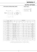
Standard Single Extension | C | Inch Single Extension 0 UNIT SIZE * - Inch Shaft has an open ended keyway, therefore no "L11" dimensions are required
Open the catalog to page 12
SERIES F MOTOR ADAPTERS DOUBLE REDUCTION UNITS IEC Flanges B14 Column 12 entry for units type G (Column 10) MOTOR / FRAME FLANGE UNIT SIZE, NUMBER OF REDUCTIONS, REVISION NUMBER F0322 F0422 Motor codes marked with * are not suitable for use with Kibo Bushing Limited Availability / Non Preferred IEC Flanges B5 Column 12 entry for units type G (Column 10) RATIO COVERAGE MOTOR / FRAME FLANGE UNIT SIZE, NUMBER OF REDUCTIONS, REVISION NUMBER F0322 F0422 NEMA Flanges C face Column 12 entry for units type G (Column 10) RATIO COVERAGE MOTOR / FRAME FLANGE UNIT SIZE, NUMBER OF REDUCTIONS, REVISION...
Open the catalog to page 13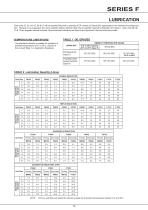
Gear units 02, 03, 04, 05, 06 & 07 will be supplied filled with a quantity of EP mineral oil (Grade 6E) appropriate to the intended mounting position. However if, as requested, the unit is supplied without lubricant then the oil quantity required is obtained from Table 2. Gear units 08, 09, 10& 12are supplied without lubricant. Recommended lubricants are listed in the Approved Lubricant scheme booklet. NOTE: Primary units filled with Grade 6E lubricant suitable for all ambient temperatures between 0oC and 35oC
Open the catalog to page 16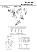
Enter | - | for units with no oil fill Unit Size MOUNTING POSITIONS - SHOWN AS MOTORIZED - APPLIES ALSO FOR REDUCERS COLUMN 14 ENTRY Column 14 Entry
Open the catalog to page 17All Radicon catalogs and technical brochures
-
Series M Helical In-Line
116 Pages
-
BR-Series-AM.
72 Pages
-
adicon-SeriesX
32 Pages
-
Radicon Series X Couplings
32 Pages
-
BR Series X Couplings
36 Pages
-
BR Cone Ring Couplings
16 Pages
-
Series J
73 Pages
-
Motor
4 Pages
-
Series E Flyer
4 Pages
-
G series
4 Pages
-
BD
4 Pages
-
Product Brochure radicon
8 Pages
-
Benzlers Screw Jacks
69 Pages
-
Series J - Shaft Mounted Gearbox
15 Pages
-
Radicon Series ET
42 Pages
-
BR Series G
71 Pages
-
Metric
8 Pages
-
Geared Pump
15 Pages
-
Series P Planetary
4 Pages
-
M series
120 Pages
-
Sala Gears
74 Pages
-
Roloid Pump
17 Pages
-
Heavy Duty Worm Gear Series ER
15 Pages
-
Screw Jacks
58 Pages
-
Series AM Worm Gear
73 Pages
-
Worm Gear Series AJ
89 Pages
-
Series BS Worm Gear
60 Pages
-
Elflex Flexible Couplings
8 Pages
-
Series H industrial gearboxes
123 Pages
-
SERIE G
71 Pages
-
C series
120 Pages
-
Geared Motor Series K
90 Pages
-
F series
119 Pages
-
Elign Gear Couplings
17 Pages
Archived catalogs
-
Worm Gears Series AH
13 Pages


