


BR-Series-AM.

BR-Series-AM.
This document provides comprehensive technical specifications and guidelines for various worm gears and mechanical drive solutions, including compliance with the ATEX Directive for explosive atmospheres.
The document details several series of gear units, such as:
- Series A: Mid-range worm gear units.
- Series P: Planetary units.
- Series J: Shaft-mounted helical speed reducers.
- Series C: Right angle drive helical worm geared motors.
- Series BD: Screwjack worm gear units.
- Series G: Helical parallel shaft and bevel helical right angle drive gear units.
- Series M: In-line helical geared motors.
- Series H: Large helical parallel shaft units.
- Series BS: Worm gear units.
- Series X: Nylicon gear coupling.
- Series K: Right angle helical bevel helical geared motors.
- Series F: Parallel shaft helical geared motors.
The document ensures compliance with the ATEX Directive 94/9/EC, providing certification details for gearboxes and geared motors.
Specifications include:
- Single Reduction Units: Sizes 100 to 200 mm centers.
- Double Reduction Units: Ratios up to 4200/1.
- Heavy Duty Stirrer Units: High bending loads.
- Cooling Tower Fan Drives: Built-in mechanical oil pump.
Mechanical and thermal service factors are used for gear unit selection based on load conditions, with tables for different load classifications and temperatures.
Applications are classified by load type to assist in gear unit selection.
Details on gearbox output shafts, including torque calculations, are provided. Normal output torque is 1970Nm, and maximum motor starting torque is 3545Nm.
Instructions for checking dimensions and overhung loads are included, with specific procedures for motorized units.
Criteria for momentary overloads and air gap checks in brake motors are outlined.
Data for motor frame sizes, including speed, efficiency, and torque, is provided.
Various mounting positions and output shaft options are detailed, with dimensions and additional features.
Details on brake motors, including operation and maintenance, are provided.
Information on motor variants and adaptors for IEC and NEMA standards is included.
Tables provide ratios and motor performance data for selecting motor and gearbox combinations.
Focus on double reduction versions with ratios from 75:1 to 4200:1, with recommendations for Series C for ratios up to 75:1.
Formula for calculating overhung loads and methods to reduce them are provided.
Advice on overhung loads and positioning of sprockets or gears is given.
Tables detail maximum permissible loads and ratings for power, torque, and efficiency.
Overhung load calculation and factors for different members are specified.
Close-coupled motorized units are only available in double reduction versions.
Recommendations for mounting sprockets or gears close to the gear unit case.
Ratings are categorized by input RPM and series, with data on power, torque, and efficiency.
Efficiency varies across configurations, with higher efficiencies at lower ratios and speeds.
Mechanical input power and output torque increase with unit size and ratio.
Consult application engineers for specific configurations and speed limits.
High-speed gearboxes can produce harmful noise levels; ear protection is recommended.
Use designated lifting points to prevent injury or damage.
Follow manufacturer instructions for handling lubricants to avoid harm.
Isolate power before working on gearboxes to prevent accidental start-up.
Store equipment in controlled environments and follow manufacturer instructions.
Allow equipment to cool before servicing to prevent burns.
Ensure backup systems and operate within limits to avoid critical speeds and vibrations.
Contact details for Benzlers and Radicon are provided for assistance.
Catalog excerpts

Series A Mid Range Worm Gear
Open the catalog to page 1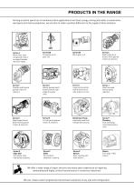
PRODUCTS IN THE RANGE Serving an entire spectrum of mechanical drive applications from food, energy, mining and metal; to automotive, aerospace and marine propulsion, we are here to make a positive difference to the supply of drive solutions. Series A Worm Gear units and geared motors in single & double reduction types Series BD Screwjack worm gear unit Series BS Worm gear unit Series C Right angle drive helical worm geared motors & reducers Series F Parallel shaft helical geared motors & reducers Series G Helical parallel shaft & bevel helical right angle drive gear units Series H Large helical...
Open the catalog to page 2
ATEX Compliance Assured Total compliance with the ATEX Directive safeguarding the use of industrial equipment in potentially explosive atmospheres is assured for users of our geared products. Certification is available for standard gearboxes and geared motors with badging displaying the ATEX zone, name and location of the manufacturer, designation of series or type, serial number, year of manufacture, Ex symbol and equipment group/category. ATEX directive 94/9/EC (also known as ATEX 95 or ATEX 100A) enforced in all EC member states. Compliance is compulsory for designers, manufacturers or suppliers...
Open the catalog to page 3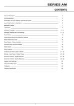
SERIES AM CONTENTS General Description __________________________________________________________________ 3 Unit Designations ____________________________________________________________________ 4 Explanation and use of Ratings and Service Factors _________________________________________ 5 Load Classification by Applications ______________________________________________________ 6 Moments of Inertia ___________________________________________________________________ 7 Lubrication _________________________________________________________________________ 8 Selection Procedure __________________________________________________________________...
Open the catalog to page 5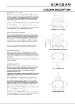
SERIES AM GENERAL DESCRIPTION Single Reduction Units (worm) This fully metric range of units of 100, 125, 160 and 200 mm centres is based on a single universal case for each size, giving a high degree of common parts and interchangeability. Under-driven, over-driven and vertical types provide a choice of shaft arrangements in meeting the requirements of a wide variety of applications in the medium power range up to 140 kW. All units are designed with hollow output bore, outputshaft can be fitted allowing handing to be changed without dismantling the unit. Series A Mid Range gives a choice of...
Open the catalog to page 6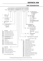
- 20 - Additional Features Paint, Lubricant, Double Oil Seal, Hold Back etc e.g. - Motor Enter - For slow speed applications where greater oil quantities are required 6, 7, 8 - Nominal Overall Ratio 15, 16, 17 - Geared Motor Powers Motor Power Required e.g. . W - STD Unit Machined Face On Left** Y - STD Unit Machined Face On Right** - STD Unit With Output Flange On Left** - STD Unit With Output Flange On Right** B - STD Unit Machined Face On Left** With Base Mounted Feet 12 - Motor Adaptor For G or A Type Unit D - STD Unit Machined Face On Right** With Base Mounted Feet For All Other Types Enter...
Open the catalog to page 7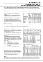
EXPLANATION & USE OF RATINGS & SERVICE FACTORS Gear unit selection is made by comparing actual loads with catalogue ratings. Catalogue ratings are based on a standard set of loading conditions, whereas actual load conditions vary according to type of application. Service Factors are therefore used to calculate an equivalent load to compare with catalogue ratings. i.e. Equivalent Load = Actual Load x Service Factor Two types of Service Factor must be considered:- Mechanical Service Factor Fm and Thermal Service Factors Ft, Fp and Fd Table1. Mechanical Service Factor Fm Mechanical Ratings and Service...
Open the catalog to page 8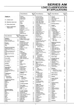
LOAD CLASSIFICATION BY APPLICATIONS Driven Machine Table 5 U = Uniform load M = Moderate shock load H = Heavy shock load = Refer to Application Engineering Cranes main hoists bridge travel trolley travel Driven Machine log haul-incline log haul-well type log turning device main log conveyor off bearing rolls planer feed chains planer floor chains planer tilting hoist re-saw merry-go-round conveyor roll cases slab conveyor small waste conveyor-belt small waste conveyor-chain sorting table tipple hoist conveyor tipple hoist drive transfer conveyors transfer rolls tray drive trimmer feed waste conveyor...
Open the catalog to page 9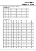
SERIES AM MOMENTS OF INERTIA MOMENTS OF INERTIA (kg cm2 ) Referred to Input Shaft SINGLE REDUCTION RATIO DOUBLE REDUCTION RATIO
Open the catalog to page 10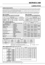
SERIES AM LUBRICATION LUBRICANT AND QUANTITY The Series A Mid Range units are despatched without oil. The oil grade is stamped on the name plate and the oil level marked on the dipstick. These are determined from the operating speed of the gear unit and the ambient temperature range, which if not given when ordering will be assumed to be 1450 rev / min input and ambient temperature range 0 to 35°C. Oil grades and oil level should therefore always be checked before installation, instructions are provided with all units despatched. To determine the oil grade refer to the appropriate table 1 or...
Open the catalog to page 11
SERIES AM SELECTION PROCEDURE EXAMPLE APPLICATION DETAILS Absorbed power of driven machine = 3.9kW Output speed of gearbox or Input speed of machine = 20rpm Application = Heavy duty, non uniformly fed bucket conveyor Duration of service (hours per day) = 10hrs Motor speed = 3 phase electric motor, 4 pole, 1450rpm Mounting position = 2 Ambient temperature = 20oC Running time (%) = 100% 2 DETERMINE MECHANICAL SERVICE FACTOR (Fm) Refer to Load Classification by Application, table 5, page 7 Application = Conveyors-heavy duty not uniformly fed apron M assembly M belt M bucket M chain M 1 DETERMINE...
Open the catalog to page 12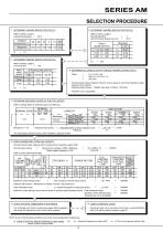
SERIES AM SELECTION PROCEDURE 7 DETERMINE THERMAL SERVICE FACTOR (Ft) 8 DETERMINE THERMAL SERVICE FACTOR (Fp) Refer to table 2, page 6 Ambient temperature = Refer to table 3, page 6 Mounting position Nominal Output Speed (rev/min) Ambient -30 temperature °C Factor Ft Ft 9 DETERMINE THERMAL SERVICE FACTOR (Fd) Refer to table 4, page 6 & running time = Input shaft speed (Rev/min) 1450 Output Speed (rev/min) % Running time per hour 10 ETERMINE ALLOWABLE OUTPUT TORQUE THERMAL RATING (Tthem) D Thermal output torque capacity (Ttherm) must be equal or more than absorbed output torque to drive machine...
Open the catalog to page 13All Radicon catalogs and technical brochures
 Series M Helical In-Line
116 Pages
 adicon-SeriesX
32 Pages
 BR Series F
117 Pages
 Radicon Series X Couplings
32 Pages
 BR Series X Couplings
36 Pages
 BR Cone Ring Couplings
16 Pages
 Series J
73 Pages
 Motor
Motor4 Pages
 Series E Flyer
4 Pages
 G series
4 Pages
 BD
BD4 Pages
 Product Brochure radicon
8 Pages
 Benzlers Screw Jacks
69 Pages
 Series J - Shaft Mounted Gearbox
15 Pages
 Radicon Series ET
42 Pages
 BR Series G
71 Pages
 Metric
8 Pages
 Geared Pump
15 Pages
 Series P Planetary
4 Pages
 M series
120 Pages
 Sala Gears
74 Pages
 Screw Jacks
58 Pages
 Roloid Pump
17 Pages
 Heavy Duty Worm Gear Series ER
15 Pages
 SERIE G
71 Pages
 C series
120 Pages
 F series
119 Pages
 Series AM Worm Gear
73 Pages
 Worm Gear Series AJ
89 Pages
 Series BS Worm Gear
60 Pages
 Elflex Flexible Couplings
8 Pages
 Series H industrial gearboxes
123 Pages
 Geared Motor Series K
90 Pages
 Elign Gear Couplings
17 Pages


Archived catalogs
 Worm Gears Series AH
13 Pages


- Industrial pump
- Pump with electric motor
- Stationary pump
- Seawater pump
- Electric gearmotor
- Planetary gearbox
- Coaxial gearhead
- Food product pump
- Right angle gearhead
- Direct current gear-motor
- Compact gearhead
- Solid-shaft gearhead
- Hollow-shaft gearhead
- Flexible coupling
- Gearbox for industrial applications
- Transmission gearhead
- Industrial electric gearmotor
- Coaxial gearmotor
- Shaft gearhead