BR Cone Ring Couplings
1 /16Pages

BR Cone Ring Couplings
1 /16Pages
Catalog excerpts

Series X Cone Ring Flexible Couplings
Open the catalog to page 1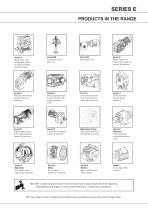
PRODUCTS IN THE RANGE PRODUCTS IN THE RANGE Serving an entire spectrum of mechanical drive applications from food, energy, mining and metal; to automotive, aerospace and marine propulsion, we are here to make a positive difference to the supply of drive solutions. Series A Worm Gear units and geared motors in single & double reduction types Series BD Screwjack worm gear unit Series BS Worm gear unit Series C Right angle drive helical worm geared motors & reducers Series F Parallel shaft helical geared motors & reducers Series G Helical parallel shaft & bevel helical right angle drive gear units...
Open the catalog to page 2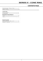
SERIES X - CONE RING CONTENTS PAGE General Information / Reference Notes Selection Procedure CONE RING General Description Unit Designations Dimensions & Specifications Engineering Data Recommended Bores - Metric and Inch Misalignment Capacities
Open the catalog to page 3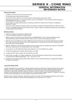
SERIES X - CONE RING GENERAL INFORMATION REFERENCE NOTES General Information - Inch/Metric conversions may not be direct conversions. - Our standards apply unless otherwise specified. - All Dimensions are for reference only and are subject to change without notice unless certified. - Unless otherwise specified, our coupling hubs will be bored for CLEARANCE FIT with a setscrew OVER the keyway or INTERFERENCE FIT without a setscrew. - Torque ratings of couplings utilising Taper-Lock bushings can differ from those that do not. Refer to our Applicaion t Engineers for details. - If we are to supply...
Open the catalog to page 4
Standard Selection Method The standard selection method can be used for most motor, turbine, or engine driven applications. The following information is required to select a gear coupling. • Kilowatt (kW) or torque (Nm). • Running rpm. • Application or type of equipment to be connected (motor to pump, drive to conveyor, etc.). • Shaft diameters. • Shaft gaps. • Physical space limitations. • Special bore or finish information and type of fit. Exceptions are High Peak Loads and Brake Applications. For these conditions, use the Formula Selection Method in the next column, or consult one of our Application...
Open the catalog to page 5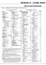
SELECTION PROCEDURE Table 1 - Coupling Service Factors for Motor ♦ and Turbine Drives Alphabetical listing of applications Alphabetical listing of applications Service Factor service Factor Direct Connected.. Refer to Application Engineer Without Flywheel.. Refer to Application Engineer Screw Pump, Progressing Cavity .. 1,25 WORK LIFT PLATFORMS ...Not Approved ♦ For engine drives, refer to Table 2. Electric motors, generators, engines, compressors and -uLhei machines rilled with sleeve ui sliaiyhl! lullei beaiings, usually lequiie limited end- float couplings. If in doubt, provide axial clearances...
Open the catalog to page 6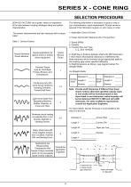
SERVICE FACTORS: are a guide, based on experience The following information is necessary to quote or ship to of the ratio between coupling catalogue rating and system your characteristics. exact requirements. Prompt service is characteristics. assured if this information is given on your inquiry or order. The system characteristics are best measured with a torque meter. Table 3 . Service Factors 1. Application: Driver & Driven 2. Power: Normal kW, Maximum kW or Torque (Nm) 5. Coupling Size and Type, e. g., Size 1070G20 6. Shaft Gap or distance between shaft ends (BE Dimension) 7. Bore Sizes:...
Open the catalog to page 7
SERIES X - CONE RING CONE RING CONE RING Pin and bush elastomer couplings
Open the catalog to page 8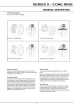
SERIES X - CONE RING GENERAL DESCRIPTION Cone Ring Couplings Pin and bush elastomer Couplings 611 Heavy Duty Straight Bored 613 Heavy Duty Taper Bushed 612 Medium Duty Straight Bored 614 Medium Duty Taper Bushed General Description Types Available Flexible Cone Ring couplings, types 61,612,613, 614 are available with bore sizes up to 355 mm diameter and a basic rated torque up to 188700 Nm. Two options are available, MEDIUM DUTY and HEAVY DUTY. Operational Details They accommodate all types of shaft misalignment met in normal operation, being a development of the old pin and bush design which...
Open the catalog to page 9
UNIT DESIGNATIONS 1 - Series X Range Cone Ring Flexible Coupling StraightBored, Heavy Duty Cone Ring Flexible Coupling Bored for taper lock bush, Medium Duty 7 - Driving Hub Bore and Keyway | M | - Metric Bore Parallel Keyway | T | - Metric Bore Taper Keyway □ - Inch Bore Parallel Keyway 0 - Inch Bore Taper Keyway 0 - Pilot Bore | C | - Customer Specified Metric 0 - Customer Specified Inch 0 - American Square Key 0 - Half Coupling 8, 9, 10 - Driving Hub Bore Diameter •+ Reference * This Page May Be Photocopied Allowing The Customer To Enter Their Order -► 15 - Additional Requirements | - | -...
Open the catalog to page 10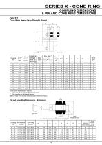
Coupling Size Larger sizes available upon request. * Up to size 05 the driving half hubs are solid. ** The coupling pin withdrawal distance. Refer to Page 4 for General Information and Reference Notes. Pin and Cone Ring Dimensions - Millimeters) Q A/F Hexagonal Head
Open the catalog to page 11
Coupling Size ** The coupling pin withdrawal distance. Refer to Page 4 for General Information and Reference Notes. Pin and Cone Ring Dimensions - Millimeters) QA/F Hexagonal Head
Open the catalog to page 12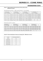
MILLIMETERS (Bores per ISO 286 - 2 - 1988 (E), Keyway to BS 4235 pt 1 : 1972 and DIN 6885)
Open the catalog to page 13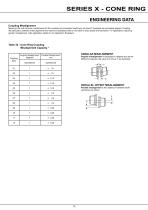
SERIES X - CONE RING Coupling Misalignment Maximum life and minimum maintenance for the coupling and connected machinery will result if couplings are accurately aligned. Coupling life expectancy between initial alignment and maximum operating limits is a function of load, speed and lubrication. For applications requiring greater misalignment, refer application details to our Application Engineers. Table 32 - Cone Ring Coupling Misalignment Capacity * ANGULAR MISALIGNMENT Angular misalignment is expressed in degrees and as the difference between the value of X minus Y, as illustrated. PARALLEL...
Open the catalog to page 14
DENMARK Benzler Transmission A/S Dalager 1 DK-2605 Brandby, Denmark Tel: +45 36 34 03 00 FINLAND Oy Benzler AB Vanha Talvitie 3C FI-00580 Helsingfors, Finland Tel: +358 9 340 1716 AUSTRALIA Radicon Transmission (Australia) PTY Ltd Australia Tel: +61 421 822 315 EUROPE Benzler TBA BV Jachthavenweg 2 NL-5928 NT Venlo Germany Tel: 0800 350 40 00 SWEDEN & NORWAY AB Benzlers Porfyrgatan 254 68 Helsingborg Sweden Tel: +46 42 18 68 00 THAILAND Radicon Transmission (Thailand) Ltd 700/43 Moo 6 Amata Nakorn Industrial Estate Tumbol Klongtumru Muang, Chonburi 20000 Thailand Tel: +66 3845 9044 UNITED KINGDOM...
Open the catalog to page 15All Radicon catalogs and technical brochures
 Series M Helical In-Line
116 Pages
 BR-Series-AM.
72 Pages
 adicon-SeriesX
32 Pages
 BR Series F
117 Pages
 Radicon Series X Couplings
32 Pages
 BR Series X Couplings
36 Pages
 Series J
73 Pages
 Motor
Motor4 Pages
 Series E Flyer
4 Pages
 G series
4 Pages
 BD
BD4 Pages
 Product Brochure radicon
8 Pages
 Benzlers Screw Jacks
69 Pages
 Series J - Shaft Mounted Gearbox
15 Pages
 Radicon Series ET
42 Pages
 BR Series G
71 Pages
 Metric
8 Pages
 Geared Pump
15 Pages
 Series P Planetary
4 Pages
 M series
120 Pages
 Sala Gears
74 Pages
 Screw Jacks
58 Pages
 Roloid Pump
17 Pages
 Heavy Duty Worm Gear Series ER
15 Pages
 SERIE G
71 Pages
 C series
120 Pages
 F series
119 Pages
 Series AM Worm Gear
73 Pages
 Worm Gear Series AJ
89 Pages
 Series BS Worm Gear
60 Pages
 Elflex Flexible Couplings
8 Pages
 Series H industrial gearboxes
123 Pages
 Geared Motor Series K
90 Pages
 Elign Gear Couplings
17 Pages


Archived catalogs
 Worm Gears Series AH
13 Pages


- Industrial pump
- Pump with electric motor
- Stationary pump
- Seawater pump
- Electric gearmotor
- Planetary gearbox
- Coaxial gearhead
- Food product pump
- Direct current gear-motor
- Right angle gearhead
- Compact gearhead
- Solid-shaft gearhead
- Hollow-shaft gearhead
- Gearbox for industrial applications
- Transmission gearhead
- Industrial electric gearmotor
- Shaft gearhead
- Coaxial gearmotor