- Company
- Products
- Catalogs
- News & Trends
- Exhibitions
CLAMPING CYLINDERS

CLAMPING CYLINDERS
This document provides comprehensive technical specifications and operational details for various hydraulic components and systems manufactured by QUIRI. It covers a range of products including cylinders, swing clamps, work supports, and hydraulic power units, each designed for specific industrial applications.
- Double acting, long stroke, flanged cylinders with a maximum force range of 11 to 112 kN at 350 bar.
- Features include domed or threaded rod ends and anti-corrosion steel bodies.
- Seal kits are available for maintenance.
- Designed for thrust or traction applications with forces from 26 to 130 kN.
- Utilizes disk springs for clamping force, released by hydraulic pressure.
- Custom models available upon request.
- PCS: Single acting with spring return; PCD: Double acting, both with forces from 13 to 131 kN.
- Features threaded holes and Heli-Coil rings for durability.
- Double acting clamps designed for efficient loading/unloading with rotation and translation capabilities.
- Maximum pressure varies with arm length, standard rotation angles at 90° ± 2°.
- Maximum pressure: 100 bar for PS26 and PLS26 models, 250 bar for HL21 and HL31 models.
- Stroke and rotation specifications vary by model, with options for custom clamping arms and corrosion treatment.
- Clamping and release phases controlled through specific ports.
- Minimum operating pressure is 30 bar, maximum temperature is 70°C.
- Proper selection of cylinders based on force and pressure requirements is crucial.
- Use appropriate tools to prevent rod rotation during installation.
- Work supports designed for precise component support during machining with locking forces from 7 to 22 kN.
- T-Lock® and R-Lock® cylinders provide secure clamping, suitable for palletization and rapid tool changes.
- CHB clamping hydraulic power unit features an electric motor and gear pump with peak pressures up to 300 bar.
- Supports CETOP 03 standard modular components.
- MDP__L and MDP__M pressure multipliers increase output pressure up to 500 bar.
- Accessories include pressure gauges, capillary hoses, and spherical accumulators.
- Filter cartridges, pressure maintenance blocks, sequence valves, controlled check valves, and solenoid block assemblies are detailed with specific pressure and flow capacities.
Catalog excerpts
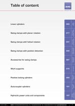
017 > Swing clampswith planar rotation 041 > Swing clampswith helical rotation 055 > Swing clamps withposition detection 067 > Accessories forswing clamps
Open the catalog to page 3
Cartridge mount cylinders - Single acting - Spring return > 004 Cartridge mount cylinders - Single acting - Hexagonal head > 005 Cartridge mount cylinders - Double acting - Threaded bottom > Linearcylinders Cartridge mount cylinders - Double acting - Threaded head > 007 Threaded cylinders - Single acting > 008 Threaded cylinders - Single acting - Long stroke > 009 Threaded cylinders - Double acting > 010 Threaded cylinders - Double acting - Long stroke > 011 Threaded cylinders - Double acting - Long stroke - Flanged > 012 Nuts for threaded cylinders > 013 Positive clamping spring cylinders >...
Open the catalog to page 5
L3 L1 b g h1 > 7f a G c D d fFlats h2 > 8,0 aR 6,1 aR a H7 > հ03 2 inim p Round off andpolish sharp anglesCylinder support plane 0,5 max.R > 2+1h 0,05 G >
Open the catalog to page 6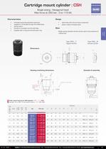
L2 L3 L1 g h1 > c d G D a7f Flats f h2 b > 8,0 aR 6,1 aR a H7 > հ03 2 pinim Round off andpolish sharp anglesCylinder support plane 0,5 max.R > 2+1h 0,05 G >
Open the catalog to page 7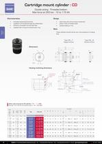
L2 L3 b g h1 L1 k > 7f a c D G d Flats f > 8,0 aR 6,1 aR հ03 ta 2 Round off andpolish sharp angles Detail A a H7 Detail A > 03 n p 3L m Cylinder support plane(piston support surface > 2e s ) r > q 0,05 0,5 max.R q Filling plugfor rod extensionFilling plugfor rod return G >
Open the catalog to page 8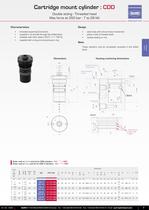
ոo d > stroke Cylinder supportsurfacePossible to recesscylinder head > 6,1 aR g+0,5 > c g > H7 203 谠 e 0,05 > 2 f n n 1+h 3 8,0 aR h 2 1L 1k inim m 2L 3L 2k Offset drilling Detail A > 2R 1 踸5 > ixam As required D > "4/1G a > 5踸 t b g 13 Detail A > 03 谸r > s P/S 2q Round off andpolish sharp angles p q1 >
Open the catalog to page 9
Filling plugG1/4'' g L2 L1 L3 b > G c d D Flats f Assembly into a drilled plateAssembly into a tapped plate Fixing nut >
Open the catalog to page 10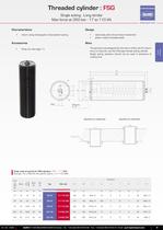
Linearcylinders L1 L2 c m > n G d D b aFilling plugG1/4'' Flats f Assembly into a drilled plateAssembly into a tapped plate Fixing nut >
Open the catalog to page 11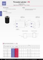
L2 L3 L1 2x mRod extension G1/4" Rod returnG1/4"Flats f A A > h G D n g d k B B A = Extension B = Return Assembly into a drilled plateAssembly into a tapped plate Fixing nut >
Open the catalog to page 12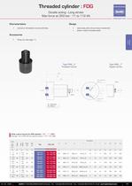
L3 L1 L4 A A > i B D A g c d h B Flats fRod extensionG1/4" Rod returnG1/4" Flats f B A = Extension B = Return >
Open the catalog to page 13
L3 L1 L4 > i D A g c d B h Mթplats f 8 (lamage)+4M踩plats f n (Lisse ou Taraud)mNota : plan d'appui Ra 0,8 >
Open the catalog to page 14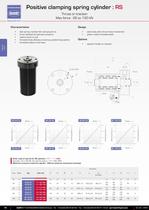
L L1 e L2 G1/4" g1 (4x at 90)D ThrustTraction > m 1d G g 2d g stroke n stroke > Stroke (mm)43210 21,5100,5 130120110100 270240220200 2 2 )rab( 2 2 2 2 2 2 )rab( )rab( )rab( )Nk( )Nk( )Nk( )Nk( Unlocking pressure Unlocking pressure Unlocking pressure Unlocking pressure Mechanical force Mechanical force Mechanical force Mechanical force 2 2 2 2 2 2 2 2 1 1 2 2
Open the catalog to page 16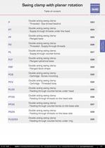
Double acting swing clamp - Threaded - Gas thread feedind > 023 Double acting swing clamp - Supply through threads under the head > 024 Double acting swing clamp - Flanged base > 025 Double acting swing clamp - Threaded - Supply through threads > 026 Swing clampswith planar rotation Double acting swing clamp - Supply through counter-bores > 027 Double acting swing clamp - Flanged cylindrical base > 028 Double acting swing clamp - Flanged block shape > 029 Double acting swing clamp - Cartridge - Screw mounting > 030 Double acting swing clamp - Cartridge - Threaded body > 032 Double acting swing...
Open the catalog to page 19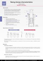
The swing clamps can clear the working area to facilitate components loading and un-loading operations. Designed for self-controled systems, they reduce non-productive time. The rotation in the plane , an exclusive system, reduces the space required for the movement. The design of this cylinder ensures optimum allocation of internal efforts, increasing longevity and reliability. all cylinders include an index on the rod . > DA all our swing clamps include venting port . damage is avoided in the event of impeded rotation. Օ no translation during pivoting therefore reduced rod seal wear. easy removal...
Open the catalog to page 20
Clamped The direction of rotation is indicated from the initial unclamped˻ position with the rod extended to the > Left clamped˻ position with the rod retracted, rod viewed from top. > Right Right = clockwise direction Left = anti-clockwise direction Standard angle of rotation : > Released Released 90 б 2 .All angle of rotation values between 0а and 90 are available on request. > A = Clamping A B B = Release The maximum forces are given for a pressure of 250 bar. This pressure is only authourised if the shortest of the three available standard arms is used. The max force (therefore the max pressure)...
Open the catalog to page 21
Swing clampswith planar rotation tighteningorun-tightening Hold F maxat250barRodd Max flow A Swept volume A B Directionof rotation TypeReference Wrench > Stroke kNmmmml/mmcm 3 41880.45.30right P 11 DX191157/050 7.40left P 11 GX191157/150 A B C D E F > figure 1 A >
Open the catalog to page 22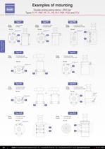
Fixing : nuts on body Fixing : 4 screws on head Fixing : 4 screws on body Supply : threads Supply : through treads Supply : counter-bores on side Venting port Top viewVenting port Top viewVenting port Venting portTop view Top viewVentingport Venting port Venting portTop view Top viewTop view Top viewTop viewVenting port A B B B A A > Swing clampswith planar rotation Fixing : 4 screws on base Fixing : 4 screws on head Supply : counter-bores on base Supply : counter-bores under head B B A A B A > Fixing : 4 screws on base Fixing : 4 screws on base Supply : threads on base Supply : counter-bores...
Open the catalog to page 24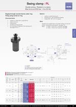
Swing clampswith planar rotation L3 Indexing X Clamped At the opposite ofthe clamping point > Left L2 p3 > Right p2 30 DA > p1谸 h 15 Dи e Released Released > d 30 k2谸 f hollowed 6 sidesextended rod DA > k1 15 c a A B Indexing X > 22,5谰 Shown in clamped position > 22,5 Ra 0.6Plane support roughness DA & DB > m2и m1 1.4 L1L A = Clamping B = Release DA = Clamping venting port for > PL11 & PL21 DA & DB = Venting port for > PL31 & PL41
Open the catalog to page 29All QUIRI catalogs and technical brochures
 LIFTING AND TOOLING
99 Pages
 HYDRAULIC CYLINDERS HVB Series
12 Pages
 GAS SPRINGS
146 Pages
 Industrial hydraulics
20 Pages
 Autolock hydraulic wise-grip
2 Pages
 QUIRIHydrosystems
24 Pages
 Nitrogen load balancer
8 Pages
 Hydraulic clamping systems
16 Pages
 LIFTING TOOLS
28 Pages
 PZ Air
8 Pages
 Vérin bloc BDS, BDE & BDA
40 Pages
 Vérin bloc S48 & BDD
20 Pages
 AUTOLOCK®
12 Pages
 QUIRI POINT ZERO
42 Pages
 BRAKING & LIFTING CYLINDER
4 Pages


Archived catalogs
 Hydraulic snubbers
32 Pages
 HYDRAULIC CAM SYSTEM
34 Pages
 HYDRAULIC CAM SYSTEM
34 Pages