- Catalogs
- Quality Transmission Components
- SPUR GEAR CALCULATIONS
SPUR GEAR CALCULATIONS
1 /5Pages

SPUR GEAR CALCULATIONS
1 /5Pages
Catalog excerpts
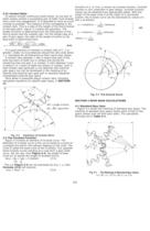
3.21 Contact Ratio To assure smooth continuous tooth action, as one pair of teeth ceases contact a succeeding pair of teeth must already have come into engagement. It is desirable to have as much overlap as possible. The measure of this overlapping is the contact ratio. This is a ratio of the length of the line-of-action to the base pitch. Figure 3-3 shows the geometry. The length-of-action is determined from the intersection of the line-of-action and the outside radii. For the simple case of a pair of spur gears, the ratio of the length of-action to the base pitch is determined from: It is good practice to maintain a contact ratio of 1 .2 or greater. Under no circumstances should the ratio drop below 1.1, calculated for all tolerances at their worst-case values. A contact ratio between 1 and 2 means that part of the time two pairs of teeth are in contact and during the remaining time one pair is in contact. A ratio between 2 and 3 means 2 or 3 pairs of teeth are always in contact. Such a high contact ratio generally is not obtained with external spur gears, but can be developed in the meshing of an internal and external spur gear pair or specially designed nonstandard external spur gears. More detail is presented about contact ratio, including calculation equations for specific gear types, in SECTION 11. 3.3 The Involute Function Figure 3-4 shows an element of involute curve. The definition of involute curve is the curve traced by a point on a straight line which rolls without slipping on the circle. The circle is called the base circle of the involutes. Two opposite hand involute curves meeting at a cusp form a gear tooth curve. We can see, from Figure 3-4, the length of base circle arc ac equals the length of straight line bc. tana = bc = rbq = q (radian) (3-5) Oc rb The q in Figure 3-4 can be expressed as inva + a, then Formula (3-5) will become: inva = tana - a (3-6) Function of a, or inva, is known as involute function. Involute function is very important in gear design. Involute function values can be obtained from appropriate tables. With the center of the base circle 0 at the origin of a coordinate system, the involute curve can be expressed by values of x and y as follows: SECTION 4 SPUR GEAR CALCULATIONS 4.1 Standard Spur Gear Figure 4-1 shows the meshing of standard spur gears. The meshing of standard spur gears means pitch circles of two gears contact and roll with each other. The calculation formulas are in Table 4-1. 342
Open the catalog to page 1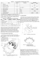
Table 4-1 The Calculation of Standard Spur Gears No. Item Symbol Formula Example Pinion Gear 1 Module m 3 2 Pressure Angle a 20º 3 Number of Teeth z1, z2* 12 24 4 Center Distance a (z1 + z2)m * 2 54.000 5 Pitch Diameter d zm 36.000 72.000 6 Base Diameter db d cos a 33.829 67.658 7 Addendum ha 1.00m 3.000 8 dedendum hf 1.25m 3.750 9 Outside Diameter da d + 2m 42.000 78.000 10 Root Diameter df d - 2.5m 28.500 64.500 * The subscripts 1 and 2 of z1 and z2 denote pinion and gear. All calculated values in Table 4-1 are based upon given module - in and number of teeth z1 and z2 If instead module m,...
Open the catalog to page 2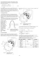
is that standard gears with teeth numbers below a critical value are automatically undercut in the generating process. The condition for no undercutting in a standard spur gear is given by the expression: This indicates that the minimum number of teeth free of undercutting decreases with increasing pressure angle. For 14.5ø the value of zc is 32, and for 20º it is 18. Thus, 20ø pressure angle gears with low numbers of teeth have the advantage of much less undercutting and, therefore, are both stronger and smoother acting. 4.4 Enlarged Pinions Undercutting of pinion teeth is undesirable because...
Open the catalog to page 3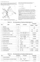
4.6 Profile Shifted Spur Gear Figure 4-8 shows the meshing of a pair of profile shifted gears. The key items in profile shifted gears are the operating (working) pitch diameters dw and the working (operating) pressure angle aw These values are obtainable from the operating (or i.e., actua center distance and the following formulas: In the meshing of profile shifted gears, it is the operating pitch circles that are in contact and roll on each other that portrays gear action. The standard pitch circles no longer are of significance; and the operating pressure angle is what matters. A standard spur...
Open the catalog to page 4All Quality Transmission Components catalogs and technical brochures
 KSUW1.5-R1
1 Page
 KKRCPFD10-1000J
1 Page
 KSAM1.5-20045
1 Page
 KSH2-20R
1 Page
 KSS0.5-30C
1 Page
 DIAMETRAL PITCH GEAR
34 Pages
 Q420 Catalog
526 Pages
 TOOTH THICKNESS
16 Pages
 Introduction to Metric Gears
15 Pages
 DESIGN OF PLASTIC GEARS
15 Pages
 WORM GEARING
5 Pages
 BEVEL GEARING
6 Pages
 HELICAL GEARS
6 Pages
 INTERNAL GEARS
4 Pages


- Compact gearhead
- Bevel gearhead
- Rack and pinion
- Straight-toothed sprocket wheel
- Straight-toothed gear
- Helical gear rack
- Metal gear
- Metal sprocket wheel
- Helical-toothed gear
- Bevel gear
- Steel gear
- Straight-toothed rack and pinion
- Hub gear
- Ground rack and pinion
- Plastic gear
- Ratchet wrench
- Shaft gear
- Cylindrical gear
- Steel rack and pinion