
- Catalogs
- Quality Transmission Components
- Introduction to Gear technologies

Introduction to Gear technologies

Introduction to Gear technologies
This section provides formulas for converting between metric and inch gear measurements, specifically for spur gears. Key formulas include calculations for pitch diameter, circular pitch, module, number of teeth, addendum, dedendum, and various types of backlash. These formulas are essential for designing and comparing gear systems using different measurement units.
Introduction to Gear Technology
This section introduces the fundamentals of gear technology, emphasizing the importance of understanding gear basics for proper design and use. It suggests a logical reading order for beginners and offers a reference for experienced designers.
Basic Geometry of Spur Gears
The section explains the basic geometry and nomenclature of spur gears, highlighting essential features such as center distance, pitch circle diameters, tooth size, number of teeth, and pressure angle. These elements are crucial for understanding gear mesh and design.
The Law of Gearing
This section outlines the requirement for constant angular velocities in gear systems, known as conjugate action. It explains the geometric relationship necessary for achieving this, known as the Law of Gearing, which ensures precision in motion transmission.
The Involute Curve
The involute curve is the basis for modern gear design due to its advantages, such as independence from center distance changes and ease of manufacturing. The section describes how involute curves are generated and their role in gear tooth design.
Pitch Circles and Module Sizes
This section discusses the importance of pitch circles and module sizes in gear design. It explains the relationship between circular pitch and module, and provides standard module sizes as defined by JIS B 1701-1973. The section also covers the conversion between metric and inch systems.
Gear Types and Axial Arrangements
Gears are categorized based on their axis orientation: parallel, intersecting, and nonparallel/nonintersecting. The section describes various gear types within these categories, such as spur, helical, bevel, worm, and screw gears, along with their applications and efficiency ranges.
Catalog excerpts

1.3.4 Conversion For those wishing to ease themselves into working with metric gears by looking at them in terms of familiar inch gearing relationships and mathematics, Table 1-5 is offered as a means to make a quick comparison. Table 1-5 Spur Gear Design Formulas To Obtain From Known Use This Formula* Pitch Diameter Module D = mN Circular Pitch Module Pc = mp = D p N Module Diametral Pitch m = 25.4 Pd Number of Teeth Module and Pitch Diameter N = D m Addendum Module a = m Dedendum Module b = 1.25m Outside Diameter Module and Pitch Diameter or Number of Teeth Do = D + 2m = m (N + 2) Root Diameter Pitch Diameter and Module DR= D - 2.5m Base Circle Diameter Pitch Diameter and Pressure Angle Db = D cos f Base Pitch Module and Pressure Angle Pb = m p cos f Tooth Thickness at Standard Pitch Diameter Module Tstd = p m 2 Center Distance Module and Number of Teeth C = m (N1 + N2) 2 Contact Ratio Outside Radii, Base Circle Radii Center Distance, Pressure Angle mp=(1Ro-1Rb)½+(2Ro-2Rb)½-Csinf m p cos f Backlash (linear) Change in Center Distance B = 2(DC)tan f Backlash (linear) Change in Tooth Thickness B = DT Backlash (linear) Along Line-of-action Linear Backlash Along Pitch Circle BLA = B cos f Backlash, Angular Linear Backlash aB = 6880 B (arc minutes) D Mm. No. of Teeth for No Undercutting Pressure Angle Nc = 2 sin²f * All linear dimensions in millimeters Symbols per Table 1-4 SECTION 2 INTRODUCTION TO GEAR TECHNOLOGY This section presents a technical coverage of gear fundamentals. It is intended as a broad coverage written in a manner that is easy to follow and to understand by anyone interested in knowing how gear systems function. Since gearing involves specialty components, it is expected that not all designers and engineers possess or have been exposed to every aspect of this subject. However, for proper use of gear components and design of gear systems it is essential to have a minimum understanding of gear basics and a reference source for details. For those to whom this is their first encounter with gear component it is suggested this technical treatise be read in the order presented so as to obtain a logical development of the subject. Subsequently, and for those already familiar with gears, this material can be used selectively in random access as a design reference. 335 Catalog Q410
Open the catalog to page 1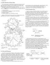
2.1 Basic Geometry Of Spur Gears The fundamentals of gearing are illustrated through the spur gear tooth, both because it is the simplest, and hence most comprehensible, and because it is the form most widely used, particularly for instruments and control systems. The basic geometry and nomenclature of a spur gear mesh is shown in Figure 2-1. The essential features of a gear mesh are: 1. Center distance. 2. The pitch circle diameters (or pitch diameters). 3. Size of teeth (or module). 4. Number of teeth. 5. Pressure angle of the contacting involutes. Details of these items along with their interdependence...
Open the catalog to page 2
contact must, __________________________________________ * Numbers in parenthesis refer to references at end of text. Fig. 2-3 Generation and Action of Gear Teeth 336 Catalog Q410
Open the catalog to page 3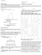
2.4 Pitch Circles Referring to Figure 2-4, the tangent to the two base circles is the line of contact, or line-of-action in gear vernacular. Where this line crosses the line-of-centers establishes the pitch point, P. This in turn sets the size of the pitch circles or as commonly called, pitch diameters The ratio of the pitch diameters gives the velocity ratio: Velocity ratio of gear 2 to gear 1 is: i = d1 (2-1) d2 25 Pitch And Module Essential to prescribing gear geometry is the size, or spacing of the teeth along the pitch circle. This is termed pitch, and there are two basic Circular pitch...
Open the catalog to page 4
P = p (2-4) m This relationship is simple to remember and permits an easy transformation from one to the other. Diametral pitch Pd is widely used in England and America to resent the tooth size. The relation between diametral pitch and other hand, a high depth tooth can increase contact ratio, but weakens the tooth. In the standard involute gear, pitch p times the number of teeth becomes the length of pitch circle: 337 Catalog Q410
Open the catalog to page 5
Metric Module and Inch Gear Preferences: Because there is no direct equivalence between the pitches in metric and inch systems, it is not possible to make direct substitutions. Further, there are preferred modules in the metric system. As an aid in using metric gears, Table 2-2 presents nearest equivalents for both systems, with the preferred sizes in bold type. 338 Catalog Q410
Open the catalog to page 6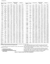
NOTE: Bold face diametral pitches and modules designate preferred values. 2.7 Gear Types And Axial Arrangements in accordance with the orientation of axes, there are three catagories of gears: 1. Parallel Axes Gears 2. Intersecting Axes Gears 3. Nonparallel and Nonintersecting Axes Gears Spur and helical gears are the parallel axes gears. Bevel gears are the intersecting axes gears. Screw or crossed helical, worm and hypoid gears handle the third category. Table 2-3 lists the gear types per axes orientation. Also, included in Table 2-3 is the theoretical efficiency range of the various gear types....
Open the catalog to page 7
Categories of Gears Types of Gears Efficiency (%) Parallel Axes Gears Spur Gear Spur Rack Internal Gear Helical Gear Helical Rack Double Helical Gear 98 ... 99.5 Intersecting Axes Gears Straight Bevel Gear Spiral Bevel Gear Zerol Gear 98 ... 99 Nonparallel and Nonintersecting Axes Gears Hypoid Worm Gear Screw Gear Gear 30 ... 90 70 ... 95 96 ... 98 339 Catalog Q410
Open the catalog to page 8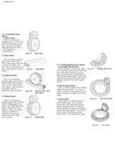
2.7.1 Parallel Axes Gears 1. Spur Gear This is a cylindrical shaped gear in which the teeth are parallel to the axis. It has the largest applications and, also, it is the easiest to manufacture. 2. Spur Rack This is a linear shaped gear which can mesh with a spur gear with any number of teeth. The spur rack is a portion of a spur gear with an infinite radius. 3. Internal Gear This is a cylindrical shaped gear but with the teeth inside the circular ring. It can mesh with a spur gear. Internal gears are often used in planetary gear systems. 4. Helical Gear This is a cylindrical shaped gear with...
Open the catalog to page 9All Quality Transmission Components catalogs and technical brochures
 KSUW1.5-R1
1 Page
 KKRCPFD10-1000J
1 Page
 KSAM1.5-20045
1 Page
 KSH2-20R
1 Page
 KSS0.5-30C
1 Page
 DIAMETRAL PITCH GEAR
34 Pages
 Q420 Catalog
526 Pages
 TOOTH THICKNESS
16 Pages
 SPUR GEAR CALCULATIONS
5 Pages
 Introduction to Metric Gears
15 Pages
 DESIGN OF PLASTIC GEARS
15 Pages
 WORM GEARING
5 Pages
 BEVEL GEARING
6 Pages
 HELICAL GEARS
6 Pages
 INTERNAL GEARS
4 Pages


- Compact gearhead
- Bevel gearhead
- Rack and pinion
- Straight-toothed sprocket wheel
- Straight-toothed gear
- Helical gear rack
- Metal gear
- Metal sprocket wheel
- Helical-toothed gear
- Straight-toothed rack and pinion
- Hub gear
- Steel gear
- Ground rack and pinion
- Plastic gear
- Ratchet wrench
- Shaft gear
- Miniature gearbox
- Steel rack and pinion