
- Catalogs
- Quality Transmission Components
- HELICAL GEARS

HELICAL GEARS

HELICAL GEARS
Helical gears have teeth twisted along a helical path, enhancing tooth strength and load capacity due to axial overlap. They are used in parallel shaft applications and crossed-helicals for skew shafts.
Generation and Fundamentals
The helical tooth form is involute in the plane of rotation, requiring a three-dimensional portrayal. The helix angle varies from the base to the outside radius, and helical gears have two pitches: normal and axial.
Equivalent Spur Gear
The concept of an equivalent spur gear helps determine helical tooth strength, with the virtual number of teeth derived from the helix angle.
Pressure Angles and Geometry
Helical gears have a normal pressure angle and a pressure angle in the plane of rotation. The normal plane geometry is crucial for gear generation, allowing a single tool to generate gears at various helix angles.
Design Considerations
Helical gears can have higher pressure angles in the plane of rotation, reducing the minimum number of teeth without undercutting. The normal system simplifies manufacturing compared to the radial system.
Helical Gear Calculations
Calculations involve determining pitch diameters, pressure angles, and center distances. The normal system uses standard values, while the radial system requires adjustments based on the helix angle.
Contact Ratio and Design
The contact ratio is enhanced by axial overlap. Design considerations include involute interference and module systems. Helical gear meshes require opposite helix directions and can adjust center distances and speed ratios by manipulating the helix angle.
Tables and Equations
The document includes tables and equations for calculating profile shifted helical gears in both normal and radial systems, as well as transformations between these systems.
1. Helical Rack and Gear Calculations
- Normal and Radial Systems: Tables provide examples and formulas for calculating shifted helical gears and racks in both systems. Key parameters include center distance, pressure angles, and profile shifts.
- Helical Rack Displacement: Displacement for one rotation of the mating gear is calculated using the radial pitch and number of teeth, with adjustments possible by modifying the helix angle.
2. Screw Gear or Crossed Helical Gear Meshes
- Features: These gears connect skew shafts and can be designed for various shaft angles. The sum of helix angles must equal the shaft angle.
- Module and Center Distance: Normal modules must be identical, and center distance can be adjusted by altering helix angles.
- Velocity Ratio: Determined by the number of teeth, not pitch diameters.
3. Screw Gear Calculations
- Conditions for meshing include identical normal modules and pressure angles. The shaft angle is determined by the sum or difference of helical angles, depending on whether the gears have the same or opposite hands.
Figures and Tables
The document includes figures illustrating gear meshes and tables with detailed formulas for calculating various gear parameters.
Catalog excerpts
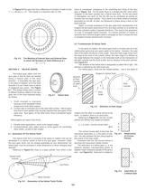
Figure 2-2 . On the plane there is a straight line AB, which when wrapped on the base cylinder has a helical trace A 6.2 Fundamentals Of Helical Teeth B is defined as the angle between the tangent to the helicoidal tooth at the intersection of the pitch cylinder and the tooth profile, and an element of the pitch cylinder. See In the plane of rotation, the helical gear tooth is involute and all of the relationships governing spur gears apply to the helical. However, the axial twist of the teeth introduces a helix angle. Since the helix angle varies from the base of the tooth to the outside radius, the helix angle Figure 6-3 . The direction of the helical twist is designated as either left or right. The direction is defined by the right-hand rule. For helical gears, there are two related pitches one in the plane of rotation and the other in a plane normal to the tooth. In addition, there is an axial pitch. Referring to In Figure 5-2 the gear train has a difference of numbers of teeth of only 1; z > 1 = 30 and z > 2 = 31. This results in a reduction ratio of 1/30. > o B > o . As the taut plane is unwrapped, any point on the line AB can be visualized as tracing an involute from the base cylinder. Thus, there is an infinite series of involutes generated by line AB, all alike, but displaced in phase along a helix on the base cylinder. Again, a concept analogous to the spur gear tooth development is to imagine the taut plane being wound from one base cylinder on to another as the base cylinders rotate in opposite directions. The result is the generation of a pair of conjugate helical involutes. If a reverse direction of rotation is assumed and a second tangent plane is arranged so that it crosses the first, a complete involute helicoid tooth is formed. a > x Figure 6-4 , the two circular pitches are defined and related as follows: p Fig. 5-2 The Meshing of Internal Gear and External Gear in which the Numbers of Teeth Difference is 1 ( z ֖ z = 1) Figure > 2 1 6-1 . This design brings forth a number of different features relative to the spur gear, two of the most important being as follows: 1. Tooth strength is improved because of the elongated helical wraparound tooth base support. 2. Contact ratio is increased due to the axial tooth overlap. Helical gears thus tend to have greater load carrying capacity than spur gears of the same size. Spur gears, on the other hand, have a somewhat higher efficiency. Helical gears are used in two forms: 1. Parallel shaft applications, which is the largest usage. 2. Crossed-helicals (also called spiral or screw gears) for connecting skew shafts, usually at right angles. Figure 6-2, there is a base cylinder from which a taut plane is unwrapped, analogous to the unwinding taut string of the spur gear in SECTION 6 HELICAL GEARS B The helical tooth form is involute in the plane of rotation and can be developed in a manner similar to that of the spur gear. However, unlike the spur gear which can be viewed essentially as two dimensional, the helical gear must be portrayed in three dimensions to show changing axial features. Referring to The helical gear differs from the spur gear in that its teeth are twisted along a helical path in the axial direction. It resembles the spur gear in the plane of rotation, but in the axial direction it is as if there were a series of staggered spur gears. See Element of Pitch Cylinder (or gear's axis)Tangent to Helical ToothPitch CylinderHelix Angle 6.1 Generation Of The Helical Tooth Fig. 6-3 Definition of Helix Angle Fig. 6-4 Relationship of Circular Pitches Fig. 6-1 Helical Gear p > n B > n = p > t cos B = normal circular pitch ( p 6-1 ) The normal circular pitch is less than the transverse radial pitch, p > t p > t , in the plane of rota-tion; the ratio between the two being equal to the cosine of the helix angle. Consistent with this, the normal module is less than the transverse (radial) module. The axial pitch of a helical gear, Figure 6-5 . Axial pitch is related to > x , is the distance between corresponding points of adjacent teeth measured parallel to the gear's axis see B Twisted Solid InvoluteTaut PlaneBase Cylinder BB A p > x A > > Fig. 6-5 Axial Pitch of a Helical Gear Fig. 6-2 Generation of the Helical Tooth Profile >
Open the catalog to page 1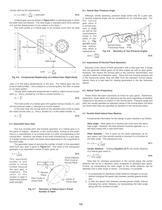
A 6.4 Helical Gear Pressure Angle Although, strictly speaking, pressure angle exists only for a gear pair, a nominal pressure angle can be considered for an individual gear. For the helical gear there is a normal pres- sure, circular pitch by the expressions: p = p cot B = ֖֖ = axial pitch ( p > n x t B 6-2 ) sin A helical gear such as shown in B , and the displacement of one rotation is the lead, Figure 6-6 is a cylindrical gear in which the teeth flank are helicoid. The helix angle in standard pitch circle cylinder is L . The tooth profile of a helical gear is an involute curve from an axial...
Open the catalog to page 2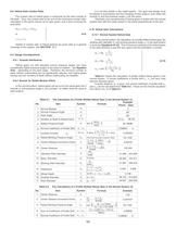
6.8 Helical Gear Contact Ratio It is not that simple in the radial system. The gear hob design must be altered in accordance with the changing of helix angle B , even when the module m The contact ratio of helical gears is enhanced by the axial overlap of the teeth. Thus, the contact ratio is the sum of the transverse contact ratio, calculated in the same manner as for spur gears, and a term involving the axial pitch. ( and the pressure angle A are the same. Obviously, the manufacturing of helical gears is easier with the normal system than with the radial system in the plane perpendicular to...
Open the catalog to page 3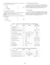
The transformation from a normal system to a radial system is accomplished by the following equations: 6.10.3 Sunderland Double Helical Gear > A representative application of radial system is a double helical gear, or herringbone gear, made with the Sunderland machine. The radial pressure angle, A x > t = x > n cos m B > t , and helix angle, B , are specified as 20 and 22.5а, respectively. The only differences from the radial system equations of cos m = ֖֖֖ > n t B > Table 6-3 are those for addendum and whole depth. Table 6-5 presents equations for a Sunderland gear. tan cos A = tan > 1 ( 6-11...
Open the catalog to page 4All Quality Transmission Components catalogs and technical brochures
 KSUW1.5-R1
1 Page
 KKRCPFD10-1000J
1 Page
 KSAM1.5-20045
1 Page
 KSH2-20R
1 Page
 KSS0.5-30C
1 Page
 DIAMETRAL PITCH GEAR
34 Pages
 Q420 Catalog
526 Pages
 TOOTH THICKNESS
16 Pages
 SPUR GEAR CALCULATIONS
5 Pages
 Introduction to Metric Gears
15 Pages
 DESIGN OF PLASTIC GEARS
15 Pages
 WORM GEARING
5 Pages
 BEVEL GEARING
6 Pages
 INTERNAL GEARS
4 Pages


- Compact gearhead
- Bevel gearhead
- Rack and pinion
- Straight-toothed sprocket wheel
- Straight-toothed gear
- Helical gear rack
- Metal gear
- Metal sprocket wheel
- Helical-toothed gear
- Bevel gear
- Straight-toothed rack and pinion
- Hub gear
- Steel gear
- Ground rack and pinion
- Plastic gear
- Ratchet wrench
- Shaft gear
- Miniature gearbox
- Steel rack and pinion