
- Catalogs
- Quality Transmission Components
- BEVEL GEARING

BEVEL GEARING

BEVEL GEARING
Bevel gears are utilized for transmitting motion and power between intersecting shafts, typically at right angles, though other angles are possible. Common gear ratios are up to 4:1, with potential for higher ratios.
Development and Geometry of Bevel Gears
Bevel gears feature tapered elements and operate on a spherical surface. The pitch diameters form frusta of cones, with the crown gear used to generate bevel gears, albeit with a simplified tooth form.
Bevel Gear Tooth Proportions
Tooth proportions adhere to the standard spur gear system, with a pressure angle capped at 20°. The Gleason system enlarges pinions with fewer teeth, referencing tooth dimensions to the outer end.
Velocity Ratio
The velocity ratio is determined by the ratio of parameters, including the pitch angle.
Forms of Bevel Teeth
Bevel teeth can be straight, spiral, or zerol. Straight bevel gears are recommended for speeds under 300 meters/min and light loads. Coniflex gears accommodate slight misalignment, while spiral bevels offer smoother motion. Zerol bevels have curved teeth with zero spiral angle.
Bevel Gear Calculations
Calculations involve parameters like shaft angle, pitch cone angles, and tooth numbers. Miter gears, a type of bevel gear, have a 90° shaft angle and equal tooth numbers, altering shaft direction without changing speed.
Gleason Straight Bevel Gears
These gears feature a profile-shifted tooth design with specific depth and clearance measurements, supported by Gleason system equations.
Standard Straight Bevel Gears
These gears lack a profile shift, with equations applicable for various shaft angles.
Gleason Spiral Bevel Gears
Spiral bevel gears have a spiral tooth flank and are part of a stub gear system, requiring matching of left-hand and right-hand pairs.
Specifications and Parameters
The document details specifications for gear components, including axial face width, diameters, and angles. Key parameters include the addendum angle and spiral angle, with formulas for calculating dimensions.
Formulas and Calculations
Formulas are provided for calculating gear dimensions and angles, crucial for ensuring proper gear function.
Gear Types and Characteristics
Different gear types, including Zerol bevel gears and worm meshes, are discussed. Zerol bevel gears have a zero spiral angle, while worm meshes connect skew shafts and are known for high velocity ratios.
Recommendations and Best Practices
Proper matching of gear pairs, especially for Zerol bevel gears, is recommended. Maintaining certain dimensional ratios optimizes gear performance.
Figures and Illustrations
Figures illustrate left-hand Zerol bevel gears and typical worm meshes, aiding in understanding gear configurations.
Catalog excerpts
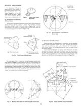
Fig. 8-1 Typical Right Angle Bevel Gear SECTION 8 BEVEL GEARING For intersecting shafts, bevel gears offer a good means of transmitting motion and power. Most transmissions occur at right angles, Figure 8-1 , but the shaft angle can be any value. Ratios up to 4:1 are common, although higher ratios are possible as well. 8.1 Development And Geometry Of Bevel Gears OP Great Circle Tooth ProfileLine of Action Pitch Line Bevel gears have tapered elements because they are generated and operate, in theory, on the surface of a sphere. Pitch diameters of mating bevel gears belong to frusta of cones, as shown in Figure 8-2a . In the full development on the surface of a sphere, a pair of meshed bevel gears are in conjugate engagement as shown in Figure 8-2b . The crown gear, which is a bevel gear having the largest possible pitch angle (defined in Fig. 8-4 Spherical Basis of Octoid Bevel Crown Gear Figure 8-5 . Common Apex of Cone FrustaTrace of Spherical Surface W > 2 8.2 Bevel Gear Tooth Proportions OO"O'P' G > 2 G Bevel gear teeth are proportioned in accordance with the standard system of tooth proportions used for spur gears. However, the pressure angle of all standard design bevel gears is limited to 20. Pinions with a small number of teeth are enlarged automatically when the design follows the Gleason system. Since bevel-tooth elements are tapered, tooth dimensions and pitch diameter are referenced to the outer end (heel). Since the narrow end of the teeth (toe) vanishes at the pitch apex (center of reference generating sphere), there is a practical limit to the length (face) of a bevel gear. The geometry and identification of bevel gear parts is given in > 1 W > 1 Pitch Cone Frusta (b) Pitch Cones and the Development Sphere Figure 8-4 . This shape gives rise to the name "octoid" for the tooth form of modern bevel gears. Fig. 8-2 Pitch Cones of Bevel Gears(a) Figure 8-3 ), is analogous to the rack of spur gearing, and is the basic tool for generating bevel gears. However, for practical reasons, the tooth form is not that of a spherical involute, and instead, the crown gear profile assumes a slightly simplified form. Although the deviation from a true spherical involute is minor, it results in a line-of-action having a figure-8 trace in its extreme extension; see > Cone Dist.Face Pitch AnglePitch Angle AddendumDedendumWhole Depth Pitch Apex to BackPitch Apex to CrownCrown to BackPitch ApexShaft Angle Pitch Dia. O.D. Root AngleFace Angle Fig. 8-3 Meshing Bevel Gear Pair with Conjugate Crown Gear O > 2 2 PO PO > Back Cone Dist. O > 1 1 O Fig. 8-5 Bevel Gear Pair Design Parameters >
Open the catalog to page 1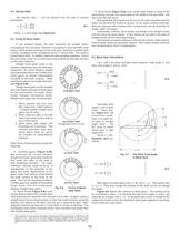
8.5 Bevel Gear Calculations Let z Zerol bevels ( Figure 8-6d ) have curved teeth similar to those of the spiral bevels, but with zero spiral angle at the middle of the face width; and they have little end thrust. Both spiral and Zerol gears can be cut on the same machines with the same circular face-mill cutters or ground on the same grinding machines. Both are produced with localized tooth contact which can be controlled for length, width, and shape. Functionally, however, Zerol bevels are similar to the straight bevels and thus carry the same ratings. In fact, Zerols can be used in the place...
Open the catalog to page 2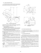
8.5.1 Gleason Straight Bevel Gears The straight bevel gear has straight teeth flanks which are along the surface of the pitch cone from the bottom to the apex. Straight bevel gears can be grouped into the Gleason type and the standard type. In this section, we discuss the Gleason straight bevel gear. The Gleason Company defined the tooth profile as: whole depth R > e bdd R > e 8.5.2. Standard Straight Bevel Gears d b > i a A bevel gear with no profile shifted tooth is a standard straight bevel gear. The applicable equations are in A spiral bevel gear is one with a spiral tooth flank as in d Table...
Open the catalog to page 3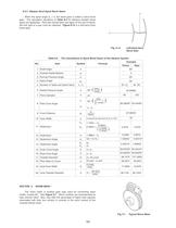
When the spiral angle B > m = 0, the bevel gear is called a Zerol bevel gear. The calculation equations of Table Figure 8-12 8-2 for Gleason straight bevel gears are applicable. They also should take care again of the rule of hands; left and right of a pair must be matched. is a left-hand Zerol bevel gear. Addendum Angle Fig. 8-12 Left-Hand Zerol Bevel Gear Example Pinion Gear Table 8-6 The Calculations of Spiral Bevel Gears of the Gleason System ItemNo. Symbol Formula Shaft Angle Outside Radial ModuleNormal Pressure AngleSpiral AngleNumber of Teeth and Spiral HandRadial Pressure AnglePitch DiameterPitch...
Open the catalog to page 6All Quality Transmission Components catalogs and technical brochures
 KSUW1.5-R1
1 Page
 KKRCPFD10-1000J
1 Page
 KSAM1.5-20045
1 Page
 KSH2-20R
1 Page
 KSS0.5-30C
1 Page
 DIAMETRAL PITCH GEAR
34 Pages
 Q420 Catalog
526 Pages
 TOOTH THICKNESS
16 Pages
 SPUR GEAR CALCULATIONS
5 Pages
 Introduction to Metric Gears
15 Pages
 DESIGN OF PLASTIC GEARS
15 Pages
 WORM GEARING
5 Pages
 HELICAL GEARS
6 Pages
 INTERNAL GEARS
4 Pages


- Compact gearhead
- Bevel gearhead
- Rack and pinion
- Straight-toothed sprocket wheel
- Straight-toothed gear
- Helical gear rack
- Metal gear
- Metal sprocket wheel
- Helical-toothed gear
- Straight-toothed rack and pinion
- Hub gear
- Steel gear
- Ground rack and pinion
- Plastic gear
- Ratchet wrench
- Shaft gear
- Miniature gearbox
- Steel rack and pinion