
- Catalogs
- Quality Transmission Components
- Bending Strength Of Spur And Helical Gears

Bending Strength Of Spur And Helical Gears

Bending Strength Of Spur And Helical Gears
Catalog excerpts
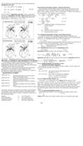
Forces acting on the driven gear can be calculated per Equations (16-25). (16-25) If the S term in Equation (16-25) is 90º, it becomes identical to Equation (16-20). Figure 16-16 presents the direction of forces in a screw gear mesh when the shaft angle S = 90º and b1 = b2 = 45º. SECTION 17 STRENGTH AND DURABILITY OF GEARS The strength of gears is generally expressed in terms of bending strength and surface durability. These are independent criteria which can have differing criticalness, although usually both are important. Discussions in this section are based upon equations published in the literature of the Japanese Gear Manufacturer Association (JGMA). Reference is made to the following JGMA specifications: Specifications of JGMA: JGMA 401-01 JGMA 402-01 JGMA 403-01 JGMA 404-01 JGMA 405-01 Bending Strength Formula of Spur Gears and Helical Gears Surface Durability Formula of Spur Gears and Helical Gears Bending Strength Formula of Bevel Gears Surface Durability Formula of Bevel Gears The Strength Formula of Worm Gears Generally, bending strength and durability specifications are applied to spur and helical gears (including double helical and internal gears) used in industrial machines in the following range: Module: Pitch Diameter: Tangential Speed: Rotating Speed: mdv n 1.5 to 25 mm 25 to 3200 mm less than 25m/sec less than 3600 rpm Conversion Formulas: Power, Torque and Force Gear strength and durability relate to the power and forces to be transmitted. Thus, the equations that relate tangential force at the pitch circle, Ft(kgf), power, P (kw), and torque, T (kgf.m) are basic to the calculations. The relations are as follows: Ft = 102P = 1.95x10⁶P = 2000T (17-1) V dwn dw P = Ftv = 10-6 = Ftdwn (17-2) 102 1.95 T = Ftdw = 974P (17-3) 2000 n where: v : Tangential Speed of Working Pitch Circle (m/sec) v : dwn 19100 dw : Working Pitch Diameter (mm) n : Rotating Speed (rpm) 17.1 Bending Strength Of Spur And Helical Gears In order to confirm an acceptable safe bending strength, it is necessary to analyze the applied tangential force at the working pitch circle, Ft, vs. allowable force, Ftlim This is stated as: Ft < Ftlim (17-4) It should be noted that the greatest bending stress is at the root of the flank or base of the dedendum. Thus, it can be stated: sF = actual stress on dedendum at root sFtlim = allowable stress Then Equation(17-4) becomes Equation(17-5) sF £ sFlim (17-5) Equation(17-6) presents the calculation of Ftlim: (17-6) Equation (17-6) can be converted into stress by Equation (17-7): (17-7) 17.1.1 Determination of Factors in the Bending Strength Equation If the gears in a pair have different blank widths, let the wider one be bw and the narrower one be bs. And if: bw - bs £ mn bw and bs can be put directly into Equation (17-6). bw - bs £ mn the wider one would be changed to bs + mn and the narrower one, bs would be unchanged. 17.1.2 Tooth Profile Factor, YF The factor YF is obtainable from Figure 17-1 based on the equivalent number of teeth, Zv and coefficient of profile shift, x, if the gear has a standard tooth profile with 20º pressure angle, per JIS B 1701. The theoretical limit of undercut is shown. Also, for profile shifted gears the limit of too narrow (sharp) a tooth top land is given. For internal gears, obtain the factor by considering the equivalent racks. 17.1.3 Load Distribution Factor, Ye Load distribution factor is the reciprocal of radial contact ratio. Ye = 1 (17-8) ea Table 17-1 shows the radial contact ratio of a standard spur gear. 400
Open the catalog to page 1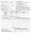
17.1.4 Helix Angle Factor, Yb Helix angle factor can be obtained from Equation(17-9). (17-9) 17.1.5 Life Factor, KL We can choose the proper life factor, KL from Table 17-2. The number of cyclic repetitions means the total loaded meshings during its lifetime. 17.1.6 Dimension Factor of Root Stress, KFX Generally, this factor is unity. KFX = 1.00 (17-10) 17.1.7 Dynamic Load Factor, KV Dynamic load factor can be obtained from Table 17-3 based on the precision of the gear and its pitch line linear speed. 17.1.8 Overload Factor, Ko Overload factor, Ko, is the quotient of actual tangential force divided...
Open the catalog to page 3All Quality Transmission Components catalogs and technical brochures
 KSUW1.5-R1
1 Page
 KKRCPFD10-1000J
1 Page
 KSAM1.5-20045
1 Page
 KSH2-20R
1 Page
 KSS0.5-30C
1 Page
 DIAMETRAL PITCH GEAR
34 Pages
 Q420 Catalog
526 Pages
 TOOTH THICKNESS
16 Pages
 SPUR GEAR CALCULATIONS
5 Pages
 Introduction to Metric Gears
15 Pages
 DESIGN OF PLASTIC GEARS
15 Pages
 WORM GEARING
5 Pages
 BEVEL GEARING
6 Pages
 HELICAL GEARS
6 Pages
 INTERNAL GEARS
4 Pages


- Compact gearhead
- Bevel gearhead
- Rack and pinion
- Straight-toothed sprocket wheel
- Straight-toothed gear
- Helical gear rack
- Metal gear
- Metal sprocket wheel
- Helical-toothed gear
- Straight-toothed rack and pinion
- Hub gear
- Steel gear
- Ground rack and pinion
- Plastic gear
- Ratchet wrench
- Shaft gear
- Miniature gearbox
- Steel rack and pinion