MEM 22
1 /10Pages

MEM 22
1 /10Pages
Catalog excerpts

Data Sheet MEM 22 www.pwb-encoders.com precision works better Absolute Encoder Magnetic PWB encoders GmbH Am Goldberg 2 D-99817 Eisenach Germany Phone: +49 3691 72580-0 Fax: +49 3691 72580-29 [email protected] www.pwb-encoders.com PWB encoders GmbH Am Goldberg 2 D-99817 Eisenach Germany [email protected] / www.pwb-encoders.com
Open the catalog to page 1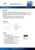
Data Sheet MEM 22 www.pwb-encoders.com precision works better Description The MEM 22 is a magnetic absolute singleturn encoder. He is a reliable low cost hollow shaft encoder that can be fixed quickly and easily on different sizes of motor shafts. The encoder is developed for brushless motors, motor feedback applications and rotational speed control. The MEM 22 is a real time system for high speed applications and rough environments. The encoder is available with to different interfaces: SSI or BiSS ®. The power supply is selectable in a wide voltage range (5V up to 30V). Power supply and signals...
Open the catalog to page 2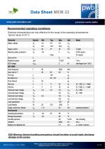
Data Sheet MEM 22 www.pwb-encoders.com precision works better Recommended operating conditions Electrical characteristics are only effective for the range of the operating temperatures. Typical values at 25 °C. Parameter Supply voltage Supply current Reverse polarity protection Rotational speed SSI / BiSS Clock frequency Scan ratio of T Time lag Monoflop time Clock interval Rise time Fall time High level output voltage Low level output voltage High level input voltage Low level input voltage Load capacitance Load Resistor Output current per channel Environment Operating temperature Storage temperature...
Open the catalog to page 3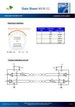
Data Sheet MEM 22 www.pwb-encoders.com precision works better Electrical interface Rotation direction (count up) Connector Cable Signal color of wire UB red GND purple Da + brown Da yellow Cl orange Cl + black Typical operating circuit PWB encoders GmbH Am Goldberg 2 D-99817 Eisenach Germany [email protected] / www.pwb-encoders.com
Open the catalog to page 4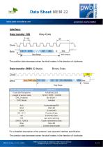
Data Sheet MEM 22 www.pwb-encoders.com precision works better Interface: Data transfer: SSI The position data decreases when the shaft rotates in the direction of clockwise Data transfer: BiSS (C-Mode) S erial interface protocol C ycle start sequence Lenght of sensor data C RC P olynom C RC Mode A cknowledge-B it S tart-B it C ontrol-B it P osition-D ata Low activ error Low activ warning C yclic redundancy code S top-B it C ontrol data master For a detailed description of the protocol, see separate interface specification. The position data decreases when the shaft rotates in the direction of...
Open the catalog to page 5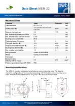
Data Sheet MEM 22 www.pwb-encoders.com precision works better Mechanical Notes Parameter Outer dimensions Required shaft length LW Max. allowable axial shaft play of motor Max. allowable radial shaft play of motor Mounting screw size (DIN 84) Tightening torque of the screws Pitch circle diameter Øc Max. mounting boss height hZ Mating connector (Molex) Total weight Moment of inertia of the hub with the magnet Protection grade according to DIN 40500 Flange bore diameter diameter ØZ Mounting boss diameter Øm Mounting considerations: The MEM 22 encoder is designed to self align by using a mounting...
Open the catalog to page 6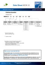
Data Sheet MEM 22 www.pwb-encoders.com precision works better Ordering information Ordering code: Encoder Interface S : SSI B : BiSS Interface Code * G : Gray B : Binary Encoder Resolution 12 : 4096 positions Motor Shaft Diameter B : 2,000 mm C : 2,500 mm D : 3,000 mm G : 4,000 mm I : 5,000 mm J : 6,000 mm K : 6,350 mm L : 8,000 mm Perfor mance S : Standard E : Extended ** Output option LF : connector without cable LS : connector + standard cable * SSI only with gray code BiSS only with binary code ** customer version Selectable and required accessories see page 10: - cable 300 mm length (UL1061...
Open the catalog to page 7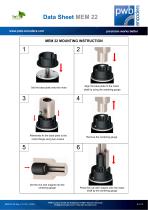
Data Sheet MEM 22 www.pwb-encoders.com precision works better Align the base plate to the motor shaft by using the centering gauge Set the base plate onto the motor , Afterwards fix the base plate to the motor flange using two screws Remove the centering gauge Set the hub with magnet into the centering gauge Press the hub with magnet onto the motor shaft by the centering gauge PWB encoders GmbH Am Goldberg 2 D-99817 Eisenach Germany [email protected] / www.pwb-encoders.com
Open the catalog to page 8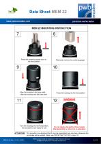
Data Sheet MEM 22 www.pwb-encoders.com precision works better Press the centering gauge down to the final position Afterwards remove the centering gauge Align the housing to the base plate, slide the housing onto the base plate Turn the housing into its final position, the encoder is now ready for use ATTENTION! Press the housing into the final position Do not rotate and pull out the encoder after assembly or when it is in operation. The encoder is so designed that it may be assembled only one time, otherwise the guarantee will be voided. Note: see IMPORTANT NOTICE (page 10) PWB encoders GmbH...
Open the catalog to page 9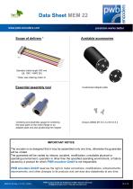
Data Sheet MEM 22 www.pwb-encoders.com precision works better Available accessories Standard cable length 300 mm (UL 1061 / AWG 28) * Note: see ordering code LS Essential assembly tool Customized adapter plate Centering and assembly gauge for centering the base plate on the motor flange or an adapter plate and also positioning the magnet IMPORTANT NOTICE The encoder is so designed that it may be assembled only one time, otherwise the guarantee will be voided. The guarantee will be voided by misuse, accident, modification, unsuitable physical or operating environment, operation in other than the...
Open the catalog to page 10All PWB encoders GmbH catalogs and technical brochures
 ASA 25
12 Pages
 AS25/AS50
20 Pages
 EBG-Head
6 Pages
 ABG
ABG9 Pages
 ME22S-PU
5 Pages
 GEO24
GEO247 Pages
 MES 25 cable
6 Pages
 MEM 25 IE cable
8 Pages
 MEM 20
2 Pages
 MEM 16
9 Pages
 MEHR 25 Y01
8 Pages
 MEHR 25 cable
7 Pages
 MEHR 25 plug
8 Pages
 MEC22
MEC228 Pages
 ME22-PU
9 Pages
 ME16
ME169 Pages
 EBG 38
6 Pages
 AEM 30
11 Pages
 AE30
AE3012 Pages
 ME 22 S
5 Pages
 MES 25
6 Pages
 AE 30 VX
9 Pages
 AE 30 F
11 Pages
 PRODUCT CATALOG
12 Pages
- Incremental encoder
- Industrial balance
- Precision weighing scale
- Linear encoder
- Incremental linear encoder
- Absolute linear encoder
- Optical linear encoder
- Angle encoder
- Mechanical balance
- Incremental angle encoder
- Magnetic angle encoder
- Absolute angle encoder
- SSI linear encoder
- Optical angle encoder
- Compact angle encoder
- Hollow-shaft angle encoder
- SSI angle encoder
- Optical encoder disc
- CAN linear encoder
- 5VDC angle encoder