
Catalog excerpts
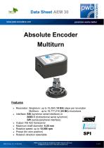
Data Sheet AEM 30 www.pwb-encoders.com precision works better Absolute Encoder Multiturn Features Resolution: Singleturn: up to 16,384 (14 Bit) steps per revolution Multiturn: up to 16,777,216 (24 Bit) revolutions Interface: SSI (synchron serial interface) or BiSS ® (bidirectional serial synchron) SPI (serial peripheral interface) Output: RS 422 transceiver Maximum shaft diameter: 6,35 mm Rotation speed: up to 10.000 rpm Preset (for zero position) Rotation direction selectable PWB encoders GmbH Am Goldberg 2 D-99817 Eisenach Germany info@pwb-encoders.com / www.pwb-encoders.com
Open the catalog to page 1
Data Sheet AEM 30 www.pwb-encoders.com precision works better Description The AEM30 is an absolute magnetic multiturn encoder. It is a reliable low cost hollow shaft encoder which can be fixed quickly and easily onto different sizes of motor shafts. The encoder is developed for absolute positioning, for brushless motors of servo motors and steppers. The AEM30 is a real time system for high speed applications and rough environments. The encoder is available with three different interfaces: SSI or BiSS ® or SPI. Power supply and signals are provided by a 8 pin Molex connector. Main...
Open the catalog to page 2
Data Sheet AEM 30 www.pwb-encoders.com precision works better Recommended operating conditions Typical values at 25 °C. Parameter Supply voltage Supply current Reverse polarity protection Absolute accuracy Relative accuracy Rotation speed SSI / BiSS / SPI Clock frequency Monoflop time High level output voltage Low level output voltage High level input voltage Low level input voltage Output current per channel adaptive Encoder Timeout Operating temperature Storage temperature Humidity exposure The angular accuracy of the datasheet can only be guaranteed by a single calibration after the...
Open the catalog to page 3
Data Sheet AEM 30 www.pwb-encoders.com precision works better Mechanical characteristics and drawings Parameter Dimensions Weight Shaft diameters Ø Motor shaft length L Max. motor mounting boss diameter D Max. motor mounting boss height H Max. motor axial shaft play Max. motor shaft eccentricity + radial play Screws for fixing Tightening torque of the screws Flange print Protection class 10.5 (see Fig.2 below) 13.0 (see Fig.2 below) 2.0 (see Fig.2 below) Note: * When the encoder is properly assembled ** Further shaft diameters on request Fig. 3 Flange print PWB encoders GmbH Am Goldberg 2...
Open the catalog to page 4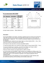
Data Sheet AEM 30 www.pwb-encoders.com precision works better Pre Power supply Clock + Ground Data Preset green blue purple brown Clock Error Reset yellow orange Encoder header connector: Description: The encoder AEM30 is a kit system, consisting a magnetic hub and a housing unit including the PCB. After assembly by the customer (see page 9/10) and after power on, the encoder can indicate the error „magnet lost“. This is caused by missing the magnet during the shipment and the assembly. For erasing the error, set the Pin „Error Reset“ high by a unique impulse (5VDC, ≥ 100ms). Then reboot...
Open the catalog to page 5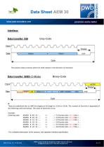
Data Sheet AEM 30 www.pwb-encoders.com precision works better Interface: Data transfer: SSI The position data increases when the shaft rotates in the direction of clockwise Data transfer: BiSS (C-Mode) 0: These are additional bits to refill the singleturn bit length to 12 bit or 16 bit. The number of Zero-bits is depended of the Ordering code (see below). The value of these bits is low. Example: Ordering code: 21 Position bits + 3 x 22 Position bits + 2 x 23 Position bits + 1 x 24 Position bits 25 Position bits + 3 x 26 Position bits + 2 x 0 bits + ... 0 bits + ... 0 bits + ... +… 0 bits +...
Open the catalog to page 6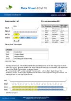
Data Sheet AEM 30 www.pwb-encoders.com precision works better Preset Select brown yellow Error Reset Sensor Data Transmission OPCODE Table Reading Sensor Data: The AEM30 latches the absolute position on the first rising edge at SCLK, when NCS is zero. Because AEM30 can output the sensor data (SD) immediately, the master can transmit the SDAD Transmission command directly. The sensor data in SPI are byte aligned. First comes 0-4 byte multiturn depending on the resolution, second are two bytes singleturn and at last one status byte including one error bit, one warning bit and six bits...
Open the catalog to page 7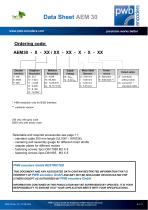
Data Sheet AEM 30 www.pwb-encoders.com precision works better Encoder Interface S : SSI B : BiSS P : SPI Motor Shaft Diameter G : 4.00 mm I : 5.00 mm J : 6.00 mm K : 6.35 mm Performance S : Standard E : Extended ** Output option LF : connector without cable LS : connector + standard cable * 14Bit resolution only for BiSS Interface ** customer version SSI only with gray code BiSS only with binary code Selectable and required accessories see page 11: - standard cable 300 mm length (UL1061 / AWG26) - centering and assembly gauge for different motor shafts - adapter plates for different motors...
Open the catalog to page 8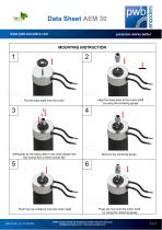
Data Sheet AEM 30 www.pwb-encoders.com precision works better MOUNTING INSTRUCTION Align the base plate to the motor shaft by using the centering gauge Put the base plate onto the motor Afterwards fix the base plate to the motor flange with two screws M3 or three screws M2 Remove the centering gauge Push the hub a little bit onto the motor shaft Press the hub onto the motor shaft by using the centering gauge PWB encoders GmbH Am Goldberg 2 D-99817 Eisenach Germany info@pwb-encoders.com / www.pwb-encoders.com
Open the catalog to page 9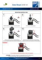
Data Sheet AEM 30 www.pwb-encoders.com precision works better MOUNTING INSTRUCTION Press the centering gauge down to the final position Remove the centering gauge Put the encoder module on the base plate and push the encoder module until it will touch the base plate When the encoder module had touched the flange, rotate the encoder module clockwise in the final position! Do not rotate the encoder after assembly or when it is in operation. ATTENTION! The encoder is designed to be assembled only one time, otherwise the guarantee will be voided. Note: see IMPORTANT NOTICE (page 10) AEM 30...
Open the catalog to page 10
Data Sheet AEM 30 www.pwb-encoders.com precision works better Cable 300 mm length UL1061 / AWG26 with female housing connector: Molex 51021-0800 with 50079-8000 terminals Essential assembly tool Available accessories Centering and assembly gauge for centering the base plate on the motor flange and also positioning the magnet Screws 2 pcs DIN 965 M3 X 8 IMPORTANT NOTICE The encoder is so designed that it may be assembled only one time, otherwise the guarantee will be voided. The guarantee will be voided by misuse, accident, modification, unsuitable physical or operating environment,...
Open the catalog to page 11All PWB encoders GmbH catalogs and technical brochures
-
ASA 25
12 Pages
-
AS25/AS50
20 Pages
-
EBG-Head
6 Pages
-
ABG
9 Pages
-
ME22S-PU
5 Pages
-
GEO24
7 Pages
-
MES 25 cable
6 Pages
-
MEM 25 IE cable
8 Pages
-
MEM 22
10 Pages
-
MEM 20
2 Pages
-
MEM 16
9 Pages
-
MEHR 25 Y01
8 Pages
-
MEHR 25 cable
7 Pages
-
MEHR 25 plug
8 Pages
-
MEC22
8 Pages
-
ME22-PU
9 Pages
-
ME16
9 Pages
-
EBG 38
6 Pages
-
AE30
12 Pages
-
ME 22 S
5 Pages
-
MES 25
6 Pages
-
AE 30 VX
9 Pages
-
AE 30 F
11 Pages
-
PRODUCT CATALOG
12 Pages


