FCU-FLEX
1 /22Pages

FCU-FLEX
1 /22Pages
Catalog excerpts
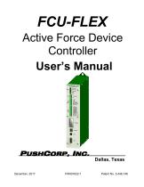
FCU-FLEX Active Force Device Controller User’s Manual Dallas, Texas Patent No. 5,448,146
Open the catalog to page 1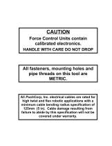
CAUTION Force Control Units contain calibrated electronics. HANDLE WITH CARE DO NOT DROP All fasteners, mounting holes and pipe threads on this tool are METRIC. All PushCorp, Inc. electrical cables are rated for high twist and flex robotic applications with a minimum cable bending radius specification of 125mm (5 in). Cable damage resulting from failure to abide by this specification will not be covered under warranty.
Open the catalog to page 2
FCU-FLEX Controller
Open the catalog to page 3
PushCorp, Inc. FCU-FLEX Controller 1 1.0 Limited Warranty Duration: One year from date of delivery to the original purchaser. Who gives this warranty (warrantor): PushCorp, Inc. Telephone: (972) 840-0208 Corporate Address: P. O. Box 181915 Dallas, Texas 75218 Shipping Address: 3001 W. Kingsley Rd. Garland, Texas 75041 Who receives this warranty (purchaser): The original purchaser (other than for purposes of resale) of the PushCorp, Inc. product What products are covered by this warranty: Any PushCorp, Inc. Adjustable Force Device or Adjustable Force Device accessory supplied or manufactured by...
Open the catalog to page 4
FCU-FLEX Controller Responsibilities of the purchaser under this warranty: A. Deliver or ship the PushCorp, Inc. product or component to PushCorp, Inc. Service Center, Dallas, TX. Freight and insurance costs, if any, must be borne by the purchaser. B. Use reasonable care in the operation and maintenance of the product as described in the owner's manual(s). When warrantor will perform repair or replacement under this warranty: Repair or replacement will be scheduled and serviced according to the normal work flow at the service center, and depending on the availability of replacement parts. Purchasers...
Open the catalog to page 5
FCU-FLEX Controller 2.0 General Overview The PushCorp, Inc. FCU-FLEX controller coupled with any PushCorp active tool provides a superior force application system. The FCU-FLEX contains a microprocessor executing proprietary control algorithms. The microprocessor enables complete stand-alone operation and provides several advanced features unique to the Active Adjustable Force System. These functions include automatic motor/tool weighing, automatic motor weight compensation, and automatic compensation of acceleration induced forces. The FCU-FLEX provides the computer control for all PushCorp...
Open the catalog to page 6
FCU-FLEX Controller 3.0 Quick Start This section gives step-by-step instructions on how to quickly get the AFD Adjustable Force Device System up and running for a quick test of its capabilities. Complete details on the FCU-FLEX features are described in the sections that follow. It is recommended that the user read the entire manual to fully understand all the aspects and features of the FCU-FLEX controller. Step 1: Consult the appropriate tool User’s Manual for pneumatic and mechanical hook-up instructions for the Active Force Tool. Step 2: Install the PushCorp AFD Dashboard configuration software....
Open the catalog to page 7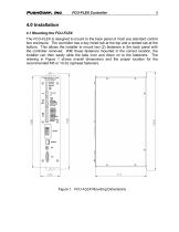
FCU-FLEX Controller 4.0 Installation 4.1 Mounting the FCU-FLEX The FCU-FLEX is designed to mount to the back panel of most any standard control box enclosure. The controller has a key holed tab at the top and a slotted tab at the bottom. This allows the installer to mount two (2) fasteners in the back panel with the controller removed. With these fasteners mounted in the correct location, the installer can then easily slide the tabs over and down on to the fasteners. The drawing in Figure 1 shows overall dimensions and the proper location for the recommended M5 or 10-32 caphead fasteners. Figure...
Open the catalog to page 8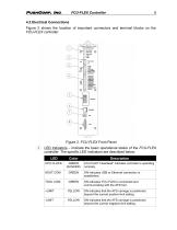
PushCorp, Inc. FCU-FLEX Controller 6
Open the catalog to page 9
PushCorp, Inc. FCU-FLEX Controller 7 @ Electrical Power Cable Connection - The supply voltage is connected via this terminal block (TB1). Care should be taken to ensure proper polarity and that a proper earth ground is connected at terminal PE. The unit accepts a nominal supply voltage of 24VDC, 2 Amps max. © Digital Outputs - 24VDC digital outputs are connected via this terminal block (TB2). Please refer to Section 5.1 Digital I/O Interface, for output descriptions. © Digital In puts - 24VDC digital inputs are connected via this terminal block (TB3). Please refer to Section 5.1 Digital I/O Interface,...
Open the catalog to page 10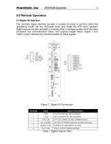
PushCorp, Inc. FCU-FLEX Controller 8 5.0 Remote Operation 5.1 Digital I/O Interface The controller digital interface provides a number of inputs to set the control the operational mode, set the command force, and weigh the AFD tool’s payload. Digital outputs are also provided to indicate when a carriage position limit has been exceeded, tool communication status, and payload weight status. Figure 7 and Tables 4 and 5 describe the functional details of these signals. Table 1. Digital Outputs (TB2)
Open the catalog to page 11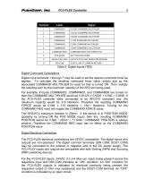
PushCorp, Inc. FCU-FLEX Controller 9 Table 2. Digital Inputs (TB3) Digital Command Calculations Digital input terminals 1 through 7 may be used to set the desired command force be applied. To calculate the resulting command force value, simply add up the associated COMMAND MULTIPLIER for each bit that is turned oN. Then multiply the resulting sum by the maximum capacity of the AFD tool being used. For example, if inputs COMMAND2, COMMAND3, and COMMAND6 are turned on then the COMMAND MULTIPLIER would be 0.03125 + 0.0625 + 0.500 = 0.5938. If the FCU-FLEX controller were connected to an AFD310 compliant...
Open the catalog to page 12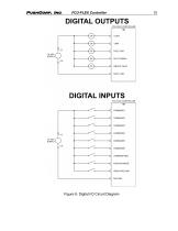
FCU-FLEX Controller Figure 8. Digital I/O Circuit Diagram
Open the catalog to page 13
FCU-FLEX Controller 5.2 Ethernet Interface The FCU-FLEX has an ethernet network connection that may be used to configure and control all aspects of the controller. The factory default network configuration is to request an IP address via DHCP, if this fails then the FCU-FLEX next attempts to set an IP address based on the AutoIP protocol. If the AutoIP configuration is successful, the FCU-FLEX will be assigned an IP address with a link-local 169.254/16 prefix (169.254.xxx.xxx). The factory default FCU-FLEX host name is “FCU-xxxxx” where “xxxxx” is the serial number of the FCU-FLEX controller....
Open the catalog to page 14


- Sanding machine
- Electric sander
- Sanding disc
- Pneumatic sander
- Belt sander
- Sander for the wood industry
- Metal abrasive disc
- Motorized spindle
- Disc sanding machine
- Machining spindle
- Sanding sanding disc
- Metal sander
- Grinding spindle
- Drilling spindle
- High-speed spindle
- Speed control sander
- Cooling spindle
- Axis compensation module
- Robot spindle
- Horizontal spindle