AFD82
1 /20Pages

AFD82
1 /20Pages
Catalog excerpts
AFD82 Adjustable Force Device Manual Dallas, Texas
Open the catalog to page 1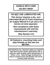
HANDLE WITH CARE DO NOT DROP DO NOT USE LUBRICATED AIR. This device requires a dry, nonlubricated 80 psi (5.5 bar) maximum air supply filtered to 5 µm and a 0.3 micron oil mist separator. Non-compliance with these requirements will void the manufacturer’s warranty. (See Section 4.4) All fasteners, mounting holes and pipe threads on this tool are METRIC. All PushCorp, Inc. electrical cables are rated for high twist and flex robotic applications with a minimum cable bending radius specification of 125mm (5 in). Cable damage resulting from failure to abide by this specification will not be covered...
Open the catalog to page 2
Copyright PushCorp, Inc. 2001. All rights reserved
Open the catalog to page 3
1.0 Limited Warranty Duration: One year from date of delivery to the original purchaser. Who gives this warranty (warrantor): PushCorp, Inc. Telephone: (972) 840-0208 Corporate Address: P. O. Box 181915 Dallas, Texas 75218 Shipping Address: 3001 W. Kingsley Rd. Garland, Texas 75041 Who receives this warranty (purchaser): The original purchaser (other than for purposes of resale) of the PushCorp, Inc. product What products are covered by this warranty: Any PushCorp, Inc. Adjustable Force Device or Adjustable Force Device accessory supplied or manufactured by the Warrantor. What is covered under...
Open the catalog to page 4
Responsibilities of the purchaser under this warranty: A. Deliver or ship the PushCorp, Inc. product or component to PushCorp, Inc. Service Center, Dallas, TX. Freight and insurance costs, if any, must be borne by the purchaser. B. Use reasonable care in the operation and maintenance of the product as described in the owner's manual(s). When warrantor will perform repair or replacement under this warranty: Repair or replacement will be scheduled and serviced according to the normal work flow at the service center, and depending on the availability of replacement parts. Purchasers requiring quicker...
Open the catalog to page 5
2.0 General Overview The PushCorp, 80 Series Passive AFD was designed as a low cost alternative to the 1100 Series Active Force Device. As such the 80 Series is a very basic unit that still incorporates several innovative features. To reduce operating friction and increase force accuracy the 80 Series uses glass pneumatic cylinders with graphite pistons, and linear ball bearings. It has two robot mounting configurations, and a table top mounting configuration. The 80 Series may be supplied to apply only a positive force, the AFD81, or both positive and negative forces, the AFD82. The 80 Series...
Open the catalog to page 6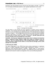
equipment, then the brackets must be removed and the problem corrected. PushCorp, Inc. can design and fabricate brackets to user supplied specifications as an option. Figure 1. Carriage bolt hole pattern The bolt pattern on the Carriage has been designed to facilitate process equipment installation. The Carriage has (14) fourteen M8x1.25 mounting holes with a depth of 0.52 inch (13 mm) to provide secure attachment points. The mounting holes are spaced as shown in Figure 1. The Carriage also has (2) two 5mm dowel pin holes to facilitate alignment. (See Figure 1 for location) These dowel pin holes...
Open the catalog to page 7
3.2.1 Mounting the AFD80-1 Vertical and AFD80-2 Horizontal The AFD80-1 and AFD80-2 are supplied with a standard Mounting Bracket shown in Figure 2. A minimum of (3) three holes should be utilized to secure the Mounting Bracket to the robot mounting flange. Figure 2. AFD80-1 and AFD80-2 Mounting Brackets Copyright PushCorp, Inc. 2001. All rights reserved
Open the catalog to page 8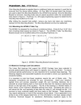
If the Mounting Bracket is supplied blank or additional holes are required, it must first be removed from the device before drilling. (4) Four M8x1.25 Socket Head Cap Screws are used to attach the Mounting Bracket to the AFD82 force devices. Once the Mounting Bracket is removed, mounting holes may be placed anywhere within the crosshatched area shown in Figure 2. PushCorp, Inc. will supply engineering support to determine the mounting hole locations at no cost. After drilling the required hole pattern, remove any burrs and clean any machining residue from the Mounting Bracket. The Mounting Bracket...
Open the catalog to page 9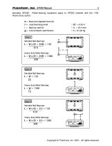
standard AFD82. Roller-bearing equations apply to AFD82 ordered with the –HD, Heavy-Duty option. Copyright PushCorp, Inc. 2001. All rights reserve
Open the catalog to page 10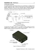
3.4 Pneumatic Connection The AFD82 Adjustable Force Devices require a dry, non-lubricated, 5 m filtered, 80 psi (5.5 Bar) maximum air supply. Failure to provide supply air to these specifications can degrade performance and will void any warranty repairs concerning pneumatic components. Filtered air is required to prevent foreign material from entering the AFD. The pneumatic supply system should be configured as shown in the Figure 4. Figure 4. Pneumatic configuration To apply force in the positive + direction, on an AFD81 or AFD82, a Supply Line must be connected to the + Supply Air Port. To...
Open the catalog to page 11
If water condensation is a problem in your air supply system, an air dryer device is highly recommended. The ideal solution is an industrial chiller dryer capable of reducing the dewpoint to less than 32 F (0C). Moisture inside the AFD will cause premature failure that will not be covered under warranty. In applications where the environment contains suspended particulate matter purge air flow must be used to ensure that the AFD remains clear of foreign matter. A Purge Port on the AFD82 (See Figure 5.) provides a pneumatic connection to supply this air flow. The port accepts a metric R 1/8...
Open the catalog to page 12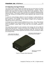
4.0 Adjusting Carriage Preload The required preload on the AFD82 Linear Rails has been set at the factory for optimal performance and, in general, should not require field adjustment. However, there are situations that could arise that cause the Linear Rails to need adjustment. Often a loose, or tight, Carriage on a new AFD is indicative of an improperly designed process equipment bracket. If the problem disappears when the brackets are removed then this is the case. Normally the Carriage will only require adjustment after removal for field service. To check for a loose Carriage, attempt to move...
Open the catalog to page 13All Pushcorp catalogs and technical brochures


- Sanding machine
- Electric sander
- Sanding disc
- Pneumatic sander
- Belt sander
- Sander for the wood industry
- Metal abrasive disc
- Motorized spindle
- Disc sanding machine
- Machining spindle
- Sanding sanding disc
- Metal sander
- Grinding spindle
- Drilling spindle
- High-speed spindle
- Speed control sander
- Cooling spindle
- Axis compensation module
- Robot spindle
- Horizontal spindle