AFD1000
1 /18Pages

AFD1000
1 /18Pages
Catalog excerpts
AFD1000 Adjustable Force Device Manual Dallas, Texas U.S. Patent No. 5,448,146
Open the catalog to page 1
CAUTION Active Force Devices contain calibrated electronics. HANDLE WITH CARE DO NOT DROP DO NOT USE LUBRICATED AIR. This device requires a dry, non-lubricated 80 to 90 psi (5.5 - 6.2 bar) air supply filtered to 5 pm and a 0.3 micron oil mist separator. Non-compliance with these requirements will void the manufacturer’s warranty. (See Section 4.3) All fasteners, mounting holes and pipe threads on this tool are METRIC. All PushCorp, Inc. electrical cables are rated for high twist and flex robotic applications with a minimum cable bending radius specification of 125mm (5 in). Cable damage resulting...
Open the catalog to page 2
RushCorr, Inc. AFD1000 Manual 1.0 Limited Warranty Duration: One year from date of delivery to the original purchaser. Who gives this warranty (warrantor): PushCorp, Inc. Telephone: (972) 840-0208 Corporate Address: P. O. Box 181915 Dallas, Texas 75218 Shipping Address: 3001 W. Kingsley Rd. Garland, Texas 75041 Who receives this warranty (purchaser): The original purchaser (other than for purposes of resale) of the PushCorp, Inc. product What products are covered by this warranty: Any PushCorp, Inc. Adjustable Force Device or Adjustable Force Device accessory supplied or manufactured by the Warrantor....
Open the catalog to page 4
Responsibilities of the purchaser under this warranty: A. Deliver or ship the PushCorp, Inc. product or component to PushCorp, Inc. Service Center, Dallas, TX. Freight and insurance costs, if any, must be borne by the purchaser. B. Use reasonable care in the operation and maintenance of the product as described in the owner's manual(s). When warrantor will perform repair or replacement under this warranty: Repair or replacement will be scheduled and serviced according to the normal work flow at the service center, and depending on the availability of replacement parts. Purchasers requiring quicker...
Open the catalog to page 5
2.0 General Overview The PushCorp, Inc. 1000 Series Adjustable Force Devices (US Patent No. 5,448,146) provide a superior force application system. The AFD can be placed in any position to enable a variety of manufacturing operations requiring a consistent applied force with .8 in. (20 mm) of compliant stroke. The AFD is designed to withstand continuous use in harsh industrial grinding, polishing, and drilling operations. The 1000 Series force tools utilize a pneumatic actuator to provide the force and a load cell force sensor to provide closed-loop feedback to an FCU1000 Active Compliance Controller....
Open the catalog to page 6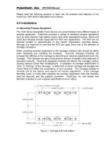
Please read the following sections to learn the full potential and features of the PushCorp 1000 Series Adjustable Force Device. 4.0 Installation 4.1 Mounting Process Equipment The 1000 Series Adjustable Force Device can accommodate many different types of process equipment. PushCorp provides a variety of standard process equipment such as weld shavers, high speed motors, plus other specialized tooling. Many end users also develop process equipment for their own applications. The AFD can be oriented parallel or perpendicular to the robotic manipulator mounting flange, although it is important...
Open the catalog to page 7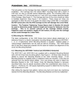
The bolt pattern on the Carriage has been designed to facilitate process equipment installation. The Carriage has (16) sixteen M6x1 mounting holes with a depth of 0.40 inch (10 mm) to provide secure attachment points. The mounting holes are spaced 5 inches (127 mm) across and on 1 inch (25.4 mm) centers along the length of the Carriage. (See Figure 1) The Carriage also has (4) four 5mm dowel pin holes to facilitate alignment. (See Figure 1 for location) These dowel pin holes are oversized to allow the pins to be glued into place using Loctite 609, or equivalent. DO NOT press pins into the AFD...
Open the catalog to page 8
2X 4imim MOUNTING PLATE LOCATING PINS 4X M8xl .25 SOCKET HEAD CAPSCREWS 3X0.422[ 10.719] FOR M10 "FLATHEAD SOCKET SCREWS 4X4mm MOUNTING PLATE LOCATING HOLES 4X M6xl SOCKET HEAD CAP SCREWS ' 3X0.422[ 10.719] FOR M10 "FLATHEAD SOCKET SCREWS
Open the catalog to page 9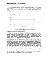
4.2.2 Mounting the AFD1000-3 Table Top The AFD1000-3 is designed for mounting on a stationary fixture. It has (3) three 0.28” (7.0 mm) mounting holes spaced as shown in Figure 3. The AFD1000-3 Table Top Mounting Bracket should not be modified without first consulting PushCorp, Inc. Figure 3. AFD1000-3 Table Top Mounting Plate 4.3 Maximum Carriage Load Calculations The Linear Rail bearings that support the 1000 Series sliding Carriage have been selected to provide optimal performance with respect to capacity, size, and low friction. To ensure continued optimal performance it is very important...
Open the catalog to page 10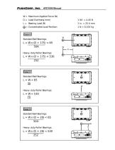
W= Maximum Applied Force (N) Concentrated Load Position Standard Ball Bearings: Heavy- duty Roller Bearings: Standard Ball Bearings: Heavy- duty Roller Bearings Standard Ball Bearings: Heavy- duty Roller Bearings:
Open the catalog to page 11
4.4 Pneumatic Connection The 1000 Series Adjustable Force Devices require a dry, non-lubricated, 5 µm filtered, 80 to 90 psi (5.5 – 6.2 bar) air supply. Failure to provide supply air to these specifications can degrade performance and will void any warranty repairs concerning pneumatic components. Filtered air is required since the high speed servo spool valve used in the AFD cannot tolerate ANY foreign material in the supply air. Additionally, a minimum 80 psi (5.5 bar) air pressure must be maintained at the supply air port for the device to operate within published specifications. Operating...
Open the catalog to page 12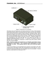
Figure 5. 1000 Series air connections The Supply Line and Purge Line to the device should be 1/4 inch or 6mm diameter flexible polyurethane tubing. The tubing should be routed to the AFD such that there are no kinks and that there is plenty of slack to allow for manipulator motion. Before inserting the Supply Line into the force device air fitting, open the Shut-Off valve to blow out any contaminates which may be in the line. The tubing can now be pushed into the self-locking fitting located on the side of the AFD. Charge the Supply Line with compressed air and verify that there are no air leaks...
Open the catalog to page 13All Pushcorp catalogs and technical brochures


- Sanding machine
- Electric sander
- Sanding disc
- Pneumatic sander
- Belt sander
- Sander for the wood industry
- Metal abrasive disc
- Motorized spindle
- Disc sanding machine
- Machining spindle
- Sanding sanding disc
- Metal sander
- Grinding spindle
- Drilling spindle
- High-speed spindle
- Speed control sander
- Cooling spindle
- Axis compensation module
- Robot spindle
- Horizontal spindle