


- Company
- Products
- Catalogs
- News & Trends
- Exhibitions
YR40.242

YR40.242
- Curve A1: Represents the recommended output current for optimal performance and longevity.
- Curve A2: Indicates the maximum allowed output current, which results in approximately half the lifetime expectancy compared to A1.
Catalog excerpts

YR40.242 12-28V, 40A, DUAL REDUNDANCY MODULE MOSFET REDUNDANCY MODULE For N+1 and 1+1 Redundant Systems Dual Input with Single Output Suitable for all DIMENSION Power Supplies Except QT20 and QTD20 Series Only 72mV Voltage Drop at 20A Output Current Only 1.7W Loss at 20A and 5.9W at 40A Output Current 160% (65A) Peak Load Capability Reverse Input Polarity Protection Full Power Between -40°C and +60°C Width only 36mm Rugged Metal Housing Easy Wiring: Distribution Terminal for Negative Pole Included 3 Year Warranty GENERAL DESCRIPTION SHORT-FORM DATA The YR40.242 is a redundancy module, which can be used to build 1+1 and N+1 redundant systems. It is equipped with two input channels, which can be connected to power supplies with up to 20A output current and one output, which can carry nominal currents up to 40A. In addition to the YR40.242, the YR40.241 is also available. This unit has an additional circuit included, which generates a supply voltage for the internal mosfets even when the output of the unit is in a short circuit condition. This makes the unit suitable for any power supplies. Input voltage DC 12-28V Input voltage range 8.4-36.4Vdc Input current 2x 0-20A 2x 20-32.5A Output current 0-40A 40-65A max. 26A The novelty of this redundancy module is the utilization of mosfets instead of diodes for the decoupling of the two input channels. This reduces the heat generation and the voltage drop between input and output. The redundancy module does not require an additional auxiliary voltage. Due to the low power losses, the unit is very slender and only requires 36mm width on the DIN-rail. Large connection terminals allow for a safe and fast installation. The large international approval package makes this unit suitable for nearly every application. ORDER NUMBERS Input to output voltage drop Power losses Temperature range Derating Dimensions **) Weight continuous for 5 seconds continuous for 5 seconds in overload*) or short circuit mode typ. 72mV input: 2x10A typ. 112mV input: 1x20A typ. 140mV input: 2x20A typ. 230mW at no load typ. 1.7W input: 2x10A typ. 2.4W input: 1x20A typ. 5.9W input: 2x20A -40°C to +70°C operational 1A/°C (output) +60 to +70°C 36x124x127mm WxHxD 280g, 0.62lb *) Currents at voltages below 6V **) Plus 4mm in depth for the screw terminal Redundancy Module Wall/ panel mount bracket Side mount bracket Apr. 2014 / Rev. 1.1 DS-YR40.242-EN All parameters are specified at 24V, 40A output current, 25°C ambient and after a 5 minutes run-in time unless otherwise noted www.pulspower.com Phone +49 89 9278 0
Open the catalog to page 1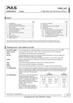
YR40.242 12-28V, 40A, DUAL REDUNDANCY MODULE The information presented in this document is believed to be accurate and reliable and may change without notice. No part of this document may be reproduced or utilized in any form without permission in writing from the publisher. PE is the abbreviation for Protective Earth and has the same meaning as the symbol Earth, Ground This document uses the term “earth” which is the same as the U.S. term “ground”. To be defined, value or description will follow later. A figure displayed with the AC or DC before the value represents a nominal voltage with standard...
Open the catalog to page 2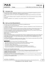
YR40.242 12-28V, 40A, DUAL REDUNDANCY MODULE 1. INTENDED USE This redundancy module is designed for installation in an enclosure and is intended for the general use such as in industrial control, office, communication, and instrumentation equipment. This redundancy module can be used with any DIMENSION power supplies except the QT20 series and the QTD20 series. Do not use this redundancy module in equipment, where malfunction may cause severe personal injury or threaten human life. This device is designed for use in hazardous, non-hazardous, ordinary or unclassified locations. 2. INSTALLATION...
Open the catalog to page 3
12-28V, 40A, DUAL REDUNDANCY MODULE I 3. INPUT AND OUTPUT CHARACTERISTICS Suitable power supplies Use only power supplies which are featured with the Hiccupptus overload behavior Input voltage Input voltage range The input circuitry must meet the SELV requirements Voltage drop, input to output Input current max 2x 13A in overload (voltage < 6V) or short circuit mode Peak input current Output current in overload (voltage < 6V) or short circuit mode Reverse current Reverse voltage voltage applied to the output, continuously allowed Output capacitance Fig. 3-1 Input to output voltage drop when both...
Open the catalog to page 4
□mnefUSIOfU Y-Series 12-28V, 40A, DUAL REDUNDANCY MODULE Power losses Standby power losses _(only one input is connected to input voltage) (only one input is connected to input voltage) (both inputs are connected to input voltages) Fig. 4-1 Power losses when both inputs draw equal current Losses = ( Ui*h + U2*l2)- UOUT* IOUT Fig. 4-2 Power losses when only one input is used _J___!__|___|___l__L p>£Al Losses = Ui * h - UOUT* IOUT All parameters are specified at 24V, 40A output current, 25°C ambient and after a 5 minutes run-in time unless otherwise noted
Open the catalog to page 5
YR40.242 12-28V, 40A, DUAL REDUNDANCY MODULE 5. LIFETIME EXPECTANCY AND MTBF The redundancy module has two input channels which are completely independent from each other. Each control circuit, auxiliary voltage source, or other circuitry in the module are designed separately for each input. The dual input redundancy module can be considered as two single redundancy modules combined together in one housing. The only common point is the circuit trace that ties the two separate circuits together at the output. The MTBF figures below are for the entire dual input module. If the MTBF number of only...
Open the catalog to page 6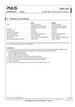
YR40.242 12-28V, 40A, DUAL REDUNDANCY MODULE 6. TERMINALS AND WIRING Type Solid wire Stranded wire American Wire Gauge Max. wire diameter Wire stripping length Screwdriver Recommended tightening torque Input Screw termination IP20 Finger safe construction. Suitable for field installation. 0.5-6mm2 0.5-4mm2 20-10 AWG 2.8mm (including ferrule) 7mm / 0.275inch 3.5mm slotted or Pozidrive No 2 0.8Nm, 7lb.in Output Screw termination IP20 Finger safe construction. Suitable for field installation. 0.5-16mm2 0.5-10mm2 22-8 AWG 5.2mm (including ferrule) 12mm / 0.5inch 3.5mm slotted or Pozidrive No 2 1.2Nm,...
Open the catalog to page 7All PULS GmbH catalogs and technical brochures
 MLY10.241
18 Pages
 MLY02.100
18 Pages
 QT40.361
28 Pages
 CD10.242
29 Pages
 XT40.361, XT40.362
21 Pages
 SL20.310
2 Pages
 SL20.300
2 Pages
 ML70.100
2 Pages
 SLR01
SLR012 Pages
 SLR10.100
2 Pages
 SL40.301
2 Pages
 SL40.300
2 Pages
 SL30.300
2 Pages
 SL20.303
2 Pages
 SL20.301
2 Pages
 SL10.309
2 Pages
 SL10.305
4 Pages
 SL10.300
2 Pages
 SL5.300
2 Pages
 SL30.100
2 Pages
 SL20.115
2 Pages
 SL20.113
2 Pages
 SL20.112
2 Pages
 SL20.111
2 Pages
 SL20.110
2 Pages
 SL20.101
2 Pages
 SL20.100
2 Pages
 SL10.106
2 Pages
 SL10.105
2 Pages
 SL10.10
2 Pages
 SL10.104
2 Pages
 SL10.101
2 Pages
 SL10.100
2 Pages
 SL5.105
2 Pages
 SL5.102
2 Pages
 SL5.100
2 Pages
 SL4.100
2 Pages
 SL2.103
2 Pages
 SL2.100
2 Pages
 ML100.200
2 Pages
 ML90.200
2 Pages
 ML100.105
2 Pages
 ML100.102
2 Pages
 ML100.100
2 Pages
 ML95.100
2 Pages
 ML60.121
23 Pages
 ML50.111
2 Pages
 ML50.109
20 Pages
 ML50.105
2 Pages
 ML50.102
2 Pages
 ML50.101
2 Pages
 ML50.100
20 Pages
 ML30.241
23 Pages
 ML30.106
2 Pages
 ML30.102
2 Pages
 ML30.101
2 Pages
 ML30.100
2 Pages
 ML15.241
23 Pages
 ML15.121
23 Pages
 ML15.051
22 Pages
 YRM2.DIODE
19 Pages
 YR80.241
17 Pages
 YR40.241
17 Pages
 YR2.DIODE
19 Pages
 XT40.722
19 Pages
 XT40.721
19 Pages
 XT40.482
20 Pages
 XT40.481
20 Pages
 XT40.362
20 Pages
 XT40.242
20 Pages
 XT40.241
20 Pages
 ZM15.SIDE
2 Pages
 ZM14.SIDE
2 Pages
 ZM13.SIDE
2 Pages
 ZM12.SIDE
2 Pages
 ZM11.SIDE
2 Pages
 ZM2.WALL
3 Pages
 ZM1.WALL
2 Pages
 ZM1.UBC10
2 Pages
 UZS24.100
3 Pages
 UF20.481
13 Pages
 UF20.241
11 Pages
 UZO12.26
2 Pages
 UZO12.07
9 Pages
 UZK12.261
8 Pages
 UZK12.071
9 Pages
 UBC10.241-N1
23 Pages
 UBC10.241
23 Pages
 UB10.245
24 Pages
 UB10.242
21 Pages
 UB10.241
23 Pages
 QT40.481
28 Pages
 QT40.241
28 Pages
 QT20.481
23 Pages
 QT20.361
23 Pages
 QT20.241-C1
23 Pages
 QT20.241
23 Pages
 QTD20.241
22 Pages
 QS10.481-D1
27 Pages
 QS10.241-D1
27 Pages
 QS40.484
28 Pages
 QS40.244
28 Pages
 QS20.481
25 Pages
 QS20.361
25 Pages
 QS20.244
25 Pages
 QS20.241-C1
26 Pages
 QS20.241-A1
26 Pages
 QS20.241
26 Pages
 QS10.481
27 Pages
 QS10.DNET
22 Pages
 QS10.301
26 Pages
 QS5.DNET
21 Pages
 QS5.241-A1
26 Pages
 QS5.241
26 Pages
 QS3.241
25 Pages
 PISA11.CLASS2
19 Pages
 PISA11.206212
23 Pages
 PISA11.203206
23 Pages
 PISA11.410
23 Pages
 PISA11.406
23 Pages
 PISA11.404
23 Pages
 PISA11.403
23 Pages
 PISA11.402
23 Pages
 PISA11.401
23 Pages
 PIC240.241D
21 Pages
 PIC120.241C
21 Pages
 PAS395
14 Pages
 CT10.481
22 Pages
 CT10.241
22 Pages
 CT5.241
21 Pages
 CT5.121
21 Pages
 CS10.481
20 Pages
 CS10.244
21 Pages
 CS10.243
19 Pages
 CS10.242
19 Pages
 CS10.241-S1
20 Pages
 CS10.241
20 Pages
 CS5.244
20 Pages
 CS5.243
19 Pages
 CS5.241-S1
20 Pages
 CS5.241-C1
20 Pages
 CS5.241
20 Pages
 CS3.241
21 Pages
 CPS20.241-C1
26 Pages
 CPS10.241
26 Pages
 CP10.242
27 Pages
 CD5.243
22 Pages
 CD5.242
22 Pages
 CD5.241-S1
23 Pages
 CD5.241-L1
21 Pages
 CD5.241
22 Pages
 CD5.121
22 Pages
 PIC120.242C
21 Pages
 PIC240.241C
20 Pages
 QS40.361
27 Pages
 QS40.481
28 Pages
 UB20.241
31 Pages
 UZK24.071
9 Pages
 UZK24.121
9 Pages
 UZO24.071
9 Pages
 UZO24.121
9 Pages
 UC10.241
27 Pages
 UC10.242
27 Pages
 YR40.245
18 Pages
Archived catalogs
 SLZ02
SLZ022 Pages
 SLZ11
SLZ112 Pages
 SLZ12
SLZ122 Pages
 SLZ14
SLZ142 Pages
 FPS300 series
32 Pages
 FPT500 series
35 Pages
 QS10.121
26 Pages
 QS10.241
28 Pages
 QS10.241-A1
27 Pages
 QS10.241-C1
27 Pages
 Selection Guide 2015/2016
25 Pages
 selection guide 2018
31 Pages
 DECENTRALIZED POWER SUPPLIES
9 Pages
 PIANO PIC
2 Pages
 PULS CP
7 Pages
 YR40.482
17 Pages
 YR80.242
17 Pages
 SLA3.100
4 Pages
 SLA4.100
4 Pages
 SLA8.100
4 Pages
 SLA8.300
4 Pages
 SLAD4.100
4 Pages
 SLD2.100
2 Pages
 SLR02
SLR022 Pages
 SLR2.100
2 Pages
 SLR5.100
2 Pages
 SLR10.108
2 Pages
 SLV20.200
4 Pages
 SLZ10-14
2 Pages
 ML60.122
23 Pages
 ML60.241
23 Pages
 ML60.242
23 Pages
 ML120.241
22 Pages
 ML120.244
21 Pages
 ML120.CLASS2
19 Pages
 CP10.121
26 Pages
 PIANO
PIANO5 Pages
 ZM3.WALL
1 Page
 CPS20.481-D1
25 Pages
 CPS20.241-D1
25 Pages
 Selection Guide 2013
19 Pages
 QS40.241, QS40.241-A1
28 Pages
 CPS20.241
25 Pages
 CPS20.361
25 Pages
 CPS20.481
25 Pages
 CPS20.121
25 Pages
 PIC120.241D_2015
22 Pages
 PIC120.241D_2014
21 Pages
 Products 2009-2010
28 Pages
 Products 2007
34 Pages


- DC power supply
- AC/DC power supply
- CE power supply
- Single-output power supply
- Power supply for industrial applications
- Circuit breaker
- Switched-mode power supply
- DC-DC converter
- Compact power supply
- DIN rail power supply
- Variable-output power supply
- Power supply with overload protection
- Single-phase power supply
- Multiple-output power supply
- Regulated power supply
- Industrial UPS
- UL power supply
- Three-phase power supply
- Current circuit breaker