XT40.242
1 /20Pages

XT40.242
1 /20Pages
Catalog excerpts

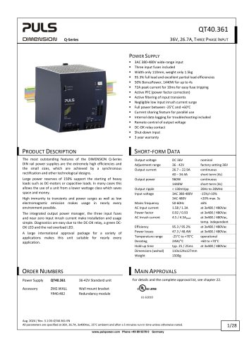
SEMI-REGULATED POWER SUPPLY • • • • • • • • • • • • • Alternative or Replacement for AC Transformer Three Phase Input – DC Output DIN-Rail Mountable Width only 96mm 95.5% Efficiency 125% Peak Power Capability No Input Inrush Current Active Input Transient Blocker Full Power Between -25°C and +60°C Easy Failure Diagnostics No Electrolytic Capacitors on Input Side Cost Effective and Robust 3 Year Warranty 2. SHORT-FORM DATA Output voltage The power supplies in the Dimension X-Series include a new and innovative concept for generating an isolated DC voltage from a three-phase mains system. A semi-regulated resonant converter enables a very compact design, maximum efficiency and extremely competitive pricing with only a small compromise in the output voltage regulation, output ripple and hold-up time. Weighing just 1.4 kg, the device provides 960 watts of continuous output power and an additional 25% power reserve for dynamic loads. The light-weight design along with compact dimensions facilitate straightforward mounting on DIN-rail. Primary use are applications involving supplies to motors, valves and other load circuits with a high power consumption, where an accurate output voltage regulation which is standard on traditional switched-mode power supplies is not required. Furthermore, these switched-mode power supplies can often replace mains transformers with rectifiers. 3. ORDER NUMBERS Power Supply Accessory Adjustment range Output current none 40A 50A Output power 960W 1200W Output ripple < 1500mVpp < 200mVpp Input voltage 3AC 400V 3AC 480V Mains frequency 50-60Hz AC Input current 1.65A / phase 1.4A / phase Power factor 0.93 AC Inrush current typ. 2A peak Efficiency 95.5% Losses 45.2W Temperature range -25°C to +70°C Derating 24W/°C Dimensions 96x124x159mm 400V Input 480V Input 24V Buffer Unit Redundancy Module Jan. 2007 / Rev. 1.0 DS-XT40.24x-EN All parameters are specified at 24V 40A, 3x400Vac (XT40.241) or 3x480Vac (XT40.242), 25°C ambient and after a 5 minutes run-in time unless otherwise noted. www.pulspower.com Phone +49 89 9278 0
Open the catalog to page 1
INTENDED USE The power supply shall only be installed and put into operation by qualified personnel. This power supply is designed for installation in an enclosure and is intended for the general use, such as in industrial control, office, communication, and instrumentation equipment. Do not use this device in aircraft, trains and nuclear equipment, where malfunctioning of the power supply may cause severe personal injury or threaten human life. PE is the abbreviation for Protective Earth and has the same meaning as the symbol Earth, Ground This document uses the term “earth” which is the same...
Open the catalog to page 2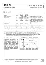
5. AC-INPUT AC input Mains arrangement AC input range Input frequency Turn-on voltage Shut-down voltage Input current Power factor **) Turn-on overshoot Start-up delay ***) Rise time *) **) ***) consult factory if one phase is earthed fully regulated output (±2%), Pout > 48W permanently allowed, see Fig. 5-1 for output voltage regulation Absolute maximum input voltage with no damage to the power supply. Output might be off at this level. ±6% see Fig. 5-2 see Fig. 5-2 at 40A, symmetrical input, see Fig. 5-4 at 40A, symmetrical input, see Fig. 5-5 see Fig. 5-3 over the entire load range, see Fig....
Open the catalog to page 3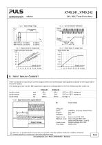
Fig. 5-2 Input voltage range Intput Voltage Start-up delay Fig. 5-4 Input current vs. output load Rise Time Fig. 5-5 Power factor vs. output load Power Factor, typ. Input Current per Phase, typ. Output Voltage fully regulated range Fig. 5-3 Turn-on behavior definitions Output Current 6. INPUT INRUSH CURRENT There is virtually no input inrush current surge as there are no electrolytic bulk-capacitors utilized on the input side of the power supply. The charging current into the EMI suppression capacitors is disregarded for the first millisecond after switch-on. Inrush current Inrush energy Inrush...
Open the catalog to page 4
7. OUTPUT Output voltage Output voltage adjustment range Output current Short-circuit current Output power Line regulation Load regulation Ripple and noise voltage *) Output capacitance The output voltage is fixed. No adjustment possible continuous, see Fig. 7-1 up to 15s with full output voltage, see Fig. 7-1 load impedance 25mOhm, see Fig. 7-1 Note: The short-circuit current is available for 0.1s continuous up to 15s see Fig. 5-1 static value, 0A 40A 0A static value, 5A 40A 5A 20Hz-2kHz, 50Ohm 2kHz to 20MHz, 50Ohm *) The ripple and noise voltage mostly consist of a mains ripple with 300Hz (50Hz...
Open the catalog to page 5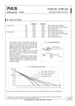
8. HOLD-UP TIME Hold-up Time Hold-up Time The energy is stored in the output capacitor. As soon as the input is turned off, the output capacitor will be discharged and the voltage will dissipate according to the curves in Fig. 8-2. The lighter the load, the longer the hold-up time. Half the load means twice the hold-up time. The hold-up time depends on the load characteristic. The curves below show the hold-up time for a load with a resistive and a constant power characteristic. The hold-up time is defined as the period of time when the input is turned off and until the output voltage falls below...
Open the catalog to page 6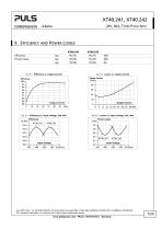
9. EFFICIENCY AND POWER LOSSES Efficiency Power losses Fig. 9-1 Efficiency vs. output current Fig. 9-2 Losses vs. output current Power Losses Fig. 9-3 Efficiency vs. input voltage, 24V, 40A Fig. 9-4 Losses vs. input voltage, 24V, 40A Output Current Power Losses Input Voltage Jan. 2007 / Rev. 1.0 DS-XT40.24x-EN All parameters are specified at 24V 40A, 3x400Vac (XT40.241) or 3x480Vac (XT40.242), 25°C ambient and after a 5 minutes run-in time unless otherwise noted. www.pulspower.com Phone +49 89 9278 0
Open the catalog to page 7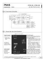
□innerusiofu -x-series I 11. FRONT SIDE AND USER ELEMENTS Output Terminals - Large screw terminal - Negative (return) appropriate wire size. JM-JE Check Input JiniUUllL Temperature Input Terminals Screw terminals Line inputs Earth) input Power Supply Indicates a normal operation. The LED is on if the output voltage is higher than 21.6V. - A steady-state light indicates an output current higher than the nominal current and that the internal shutdown timer is - A double flash indicates a phase-loss or too low/too high input voltage. A fast flash warns of an impending temperature shut-down. A shut-down...
Open the catalog to page 8All PULS GmbH catalogs and technical brochures
 MLY10.241
18 Pages
 MLY02.100
18 Pages
 QT40.361
28 Pages
 CD10.242
29 Pages
 XT40.361, XT40.362
21 Pages
 SL20.310
2 Pages
 SL20.300
2 Pages
 ML70.100
2 Pages
 SLR01
SLR012 Pages
 SLR10.100
2 Pages
 SL40.301
2 Pages
 SL40.300
2 Pages
 SL30.300
2 Pages
 SL20.303
2 Pages
 SL20.301
2 Pages
 SL10.309
2 Pages
 SL10.305
4 Pages
 SL10.300
2 Pages
 SL5.300
2 Pages
 SL30.100
2 Pages
 SL20.115
2 Pages
 SL20.113
2 Pages
 SL20.112
2 Pages
 SL20.111
2 Pages
 SL20.110
2 Pages
 SL20.101
2 Pages
 SL20.100
2 Pages
 SL10.106
2 Pages
 SL10.105
2 Pages
 SL10.10
2 Pages
 SL10.104
2 Pages
 SL10.101
2 Pages
 SL10.100
2 Pages
 SL5.105
2 Pages
 SL5.102
2 Pages
 SL5.100
2 Pages
 SL4.100
2 Pages
 SL2.103
2 Pages
 SL2.100
2 Pages
 ML100.200
2 Pages
 ML90.200
2 Pages
 ML100.105
2 Pages
 ML100.102
2 Pages
 ML100.100
2 Pages
 ML95.100
2 Pages
 ML60.121
23 Pages
 ML50.111
2 Pages
 ML50.109
20 Pages
 ML50.105
2 Pages
 ML50.102
2 Pages
 ML50.101
2 Pages
 ML50.100
20 Pages
 ML30.241
23 Pages
 ML30.106
2 Pages
 ML30.102
2 Pages
 ML30.101
2 Pages
 ML30.100
2 Pages
 ML15.241
23 Pages
 ML15.121
23 Pages
 ML15.051
22 Pages
 YRM2.DIODE
19 Pages
 YR80.241
17 Pages
 YR40.241
17 Pages
 YR2.DIODE
19 Pages
 XT40.722
19 Pages
 XT40.721
19 Pages
 XT40.482
20 Pages
 XT40.481
20 Pages
 XT40.362
20 Pages
 XT40.241
20 Pages
 ZM15.SIDE
2 Pages
 ZM14.SIDE
2 Pages
 ZM13.SIDE
2 Pages
 ZM12.SIDE
2 Pages
 ZM11.SIDE
2 Pages
 ZM2.WALL
3 Pages
 ZM1.WALL
2 Pages
 ZM1.UBC10
2 Pages
 UZS24.100
3 Pages
 UF20.481
13 Pages
 UF20.241
11 Pages
 UZO12.26
2 Pages
 UZO12.07
9 Pages
 UZK12.261
8 Pages
 UZK12.071
9 Pages
 UBC10.241-N1
23 Pages
 UBC10.241
23 Pages
 UB10.245
24 Pages
 UB10.242
21 Pages
 UB10.241
23 Pages
 QT40.481
28 Pages
 QT40.241
28 Pages
 QT20.481
23 Pages
 QT20.361
23 Pages
 QT20.241-C1
23 Pages
 QT20.241
23 Pages
 QTD20.241
22 Pages
 QS10.481-D1
27 Pages
 QS10.241-D1
27 Pages
 QS40.484
28 Pages
 QS40.244
28 Pages
 QS20.481
25 Pages
 QS20.361
25 Pages
 QS20.244
25 Pages
 QS20.241-C1
26 Pages
 QS20.241-A1
26 Pages
 QS20.241
26 Pages
 QS10.481
27 Pages
 QS10.DNET
22 Pages
 QS10.301
26 Pages
 QS5.DNET
21 Pages
 QS5.241-A1
26 Pages
 QS5.241
26 Pages
 QS3.241
25 Pages
 PISA11.CLASS2
19 Pages
 PISA11.206212
23 Pages
 PISA11.203206
23 Pages
 PISA11.410
23 Pages
 PISA11.406
23 Pages
 PISA11.404
23 Pages
 PISA11.403
23 Pages
 PISA11.402
23 Pages
 PISA11.401
23 Pages
 PIC240.241D
21 Pages
 PIC120.241C
21 Pages
 PAS395
14 Pages
 CT10.481
22 Pages
 CT10.241
22 Pages
 CT5.241
21 Pages
 CT5.121
21 Pages
 CS10.481
20 Pages
 CS10.244
21 Pages
 CS10.243
19 Pages
 CS10.242
19 Pages
 CS10.241-S1
20 Pages
 CS10.241
20 Pages
 CS5.244
20 Pages
 CS5.243
19 Pages
 CS5.241-S1
20 Pages
 CS5.241-C1
20 Pages
 CS5.241
20 Pages
 CS3.241
21 Pages
 CPS20.241-C1
26 Pages
 CPS10.241
26 Pages
 CP10.242
27 Pages
 CD5.243
22 Pages
 CD5.242
22 Pages
 CD5.241-S1
23 Pages
 CD5.241-L1
21 Pages
 CD5.241
22 Pages
 CD5.121
22 Pages
 PIC120.242C
21 Pages
 PIC240.241C
20 Pages
 QS40.361
27 Pages
 QS40.481
28 Pages
 UB20.241
31 Pages
 UZK24.071
9 Pages
 UZK24.121
9 Pages
 UZO24.071
9 Pages
 UZO24.121
9 Pages
 UC10.241
27 Pages
 UC10.242
27 Pages
 YR40.242
17 Pages
 YR40.245
18 Pages

Archived catalogs
 SLZ02
SLZ022 Pages
 SLZ11
SLZ112 Pages
 SLZ12
SLZ122 Pages
 SLZ14
SLZ142 Pages
 FPS300 series
32 Pages
 FPT500 series
35 Pages
 QS10.121
26 Pages
 QS10.241
28 Pages
 QS10.241-A1
27 Pages
 QS10.241-C1
27 Pages
 Selection Guide 2015/2016
25 Pages
 selection guide 2018
31 Pages
 DECENTRALIZED POWER SUPPLIES
9 Pages
 PIANO PIC
2 Pages
 PULS CP
7 Pages
 YR40.482
17 Pages
 YR80.242
17 Pages
 SLA3.100
4 Pages
 SLA4.100
4 Pages
 SLA8.100
4 Pages
 SLA8.300
4 Pages
 SLAD4.100
4 Pages
 SLD2.100
2 Pages
 SLR02
SLR022 Pages
 SLR2.100
2 Pages
 SLR5.100
2 Pages
 SLR10.108
2 Pages
 SLV20.200
4 Pages
 SLZ10-14
2 Pages
 ML60.122
23 Pages
 ML60.241
23 Pages
 ML60.242
23 Pages
 ML120.241
22 Pages
 ML120.244
21 Pages
 ML120.CLASS2
19 Pages
 CP10.121
26 Pages
 PIANO
PIANO5 Pages
 ZM3.WALL
1 Page
 CPS20.481-D1
25 Pages
 CPS20.241-D1
25 Pages
 Selection Guide 2013
19 Pages
 QS40.241, QS40.241-A1
28 Pages
 CPS20.241
25 Pages
 CPS20.361
25 Pages
 CPS20.481
25 Pages
 CPS20.121
25 Pages
 PIC120.241D_2015
22 Pages
 PIC120.241D_2014
21 Pages
 Products 2009-2010
28 Pages
 Products 2007
34 Pages


- Lumibird DC power supply
- Lumibird AC/DC power supply
- CE power supply
- Single-output power supply
- Switching power supply
- Power supply for industrial applications
- Circuit breaker
- DC-DC converter
- Power supply with overload protection
- Compact power supply
- DIN rail power supply
- Variable-output power supply
- Single-phase power supply
- Multiple-output power supply
- Regulated power supply
- Industrial UPS
- Current circuit breaker
- Three-phase power supply
- Voltage circuit breaker