UF20.241
1 /11Pages

UF20.241
1 /11Pages
Catalog excerpts

Buffering with electrolytic capacitors instead of lead batteries Buffering of 24V loads Minimum hold-up time 0.2s at 20A Longer hold-up time at lower loads Clear status indication by status LED and signaling terminals Quick-connect spring-clamp terminals 3 Year warranty The buffer unit is a supplementary device for regulated DC24V power supplies. It buffers load currents during typical mains faults and load peaks. Rated voltage Voltage range Output voltage Working principle In times when the power DC supply provides sufficient Discharge voltages, the buffer unit stores energy in integrated electrolytic capacitors. In case of mains voltage fault, this energy is released again in a regulated process. Bridges mains faults without interruption Statistic show that 80% of DC Buffer Unit all mains fault lasts less than 0.2s. These mains faults are completely bridged by the buffer unit. This increases the reliability of the system as a whole. Extended hold-up time Once mains power fails or is switched off, the buffer DC Buffer Unit unit will continue to provide the load current for a defined period of time. Process data can be saved and processes can be terminated before the DC power switches off. Controlled restarts are subsequently possible. 3. ORDER NUMBERS Buffer Unit Accessory Output current Hold-up time Charging current Charging time Input current Power dissipation Temperature range Dimensions standby mode standby mode operational WxHxD Easy to handle, expandable and maintanance-free The buffer unit does not require Power Buffer any control wiring. It can be AC Supply Unit(s) added parallel to the load circuit at any given point. Buffer units DC can be switched in parallel to increase the output ampacity or the hold-up time. 4. MARKINGS 24, 20A, 200ms Wall mounting bracket Side mounting bracket Mating connector, Part of delivery May 2013 / Rev. 1.3 / DS-UF20.241-EN All parameters are specified at 24V, 20A, 25°C ambient and after a 5 minutes run-in time unless otherwise noted. www.pulspower.com Phone +49 89 9278 0
Open the catalog to page 1
INSTALLATION NOTES Mounting Orientation: The power terminal shall be located on top of the unit. Cooling Convection cooled, no forced air cooling required. Do not obstruct air flow! Installation clearances: Recommended installation clearances: 40mm on top of the unit, 20mm on the bottom of the unit, 0mm (or 15mm in case the adjacent device is a heat source) on the left and right side of the unit Intended use This buffer unit has been designed for use in panel board installations or other building-in applications where a suitable mechanical enclosure shall be provided to fulfil local requirements....
Open the catalog to page 2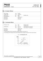
5. STANDBY MODE Input voltage Voltage range Input current Power dissipation Status lamp Active signal Ready signal DC 24V 24-28.8Vdc 80mA 1.9W permanent on high ohmic low ohmic Charging mode Charging mode 29s / 21s flashes 1.25Hz high ohmic high ohmic Standby mode 6. CHARGING MODE Charging current Charging time Status lamp Active signal Ready signal 1) Initial charging is the first charge after voltage is applied to the buffer unit. 2) Re-charging is the charging of the internal capacitors after voltage interruptions shorter than 2minutes. Fig. 6-1 Re-charging time, 24V Charge May 2013 / Rev....
Open the catalog to page 3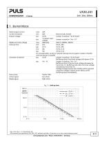
7. BUFFER MODE Rated output current Current limitation Output voltage Ripple and noise voltage Hold-up time Activation threshold Status lamp Active signal Ready signal 20A 20A Electronically limited 22.5V Jumper in position “22.5V fixed” 1V below input typ. Jumper in position “Vin –1V” voltage max. 200mVpp 20Hz to 20MHz, 50Ohm min. 0.2s 22.5V, 20A typ. 0.31s 22.5V, 20A min. 28s 22.5V, 0.1A typ. 43s 22.5V, 0.1A To increase buffer current or extend hold-up time any given number of buffer units can be put in parallel typ. 22.5V Jumper in position “22.5V fixed” Buffering starts if terminal voltage...
Open the catalog to page 4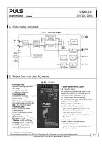
8. FUNCTIONAL DIAGRAM Fig. 8-1 Functional diagram Status lamp Buffer Capacitor Charger & Inrush Limiter Safety and OverVoltage Protection ReversePolarity Protection Buffer Capacitor Shut-Down Buffer Capacitor Discharger Buffer Capacitor Chassis Ground Input / Output Voltage Monitor Back-up Level Selector Ready Monitor Active Monitor 9. FRONT SIDE AND USER ELEMENTS Fig. 9-1 I/O Power Port Quick-connect spring-clamp terminals, + Positive terminal - Negative terminal Chassis Ground to bond the housing Back-up threshold jumper 1-2: Variable mode Unit switches to buffer mode when input voltage decreases...
Open the catalog to page 5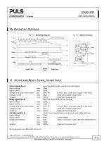
10. OPERATING DIAGRAM Fig. 10-1 Operating diagram V Mains Fig. 10-2 Signals schematic Hold-up Time Power Supply t Optocoupler high ohmic Optocoupler high ohmic Charging Mode Buffer Mode 11. ACTIVE AND READY SIGNAL, INHIBIT INPUT Active signal (Pin 7) Signal voltage Signal current Voltage drop across opto-coupler Leakage current Isolation Ready signal (Pin 8) Signal voltage Signal current Voltage drop across opto-coupler Leakage current Isolation Inhibit input (Pin 9) Signal voltage Signal current Shut-down threshold Isolation low ohmic while buffer capacitors are discharging 35Vdc 10mA 0.9V /...
Open the catalog to page 6
12. TERMINALS AND WIRING Power terminal Type Solid wire Stranded wire AWG Ferrules Pull-out force Wire stripping length Bi-stable, quick-connect spring clamp terminals. IP20 Finger safe construction. Suitable for field- and factory installation. Shipped in open position. 2 0.5-6mm 0.5-4mm2 20-10AWG Allowed, but not required 10AWG:80N, 12AWG:60N, 14AWG:50N, 16AWG:40N (according to UL486E) 10mm / 0.4inch Fig. 12-1 Connecting a wire Use appropriate copper cables, that are designed for an operating temperature of 60°C Follow national installation codes and regulations! Ensure that all strands of...
Open the catalog to page 7
14. EMC The unit is suitable for applications in industrial environment as well as in residential, commercial and light industry environment without any restrictions. CE mark is in conformance with EMC guideline 89/336/EEC and 93/68/EEC and the low-voltage directive (LVD) 73/23/EWG. A detailed EMC Report is available on request EMC Immunity Electrostatic discharge 1) Electromagnetic RF field Fast transients (Burst) Surge voltage Conducted disturbance Contact discharge Air discharge 80MHz-1GHz + +/housing 0,15-80MHz Criterion A Criterion A Criterion A Criterion A Criterion A Criterion A Criterion...
Open the catalog to page 8All PULS GmbH catalogs and technical brochures
 MLY10.241
18 Pages
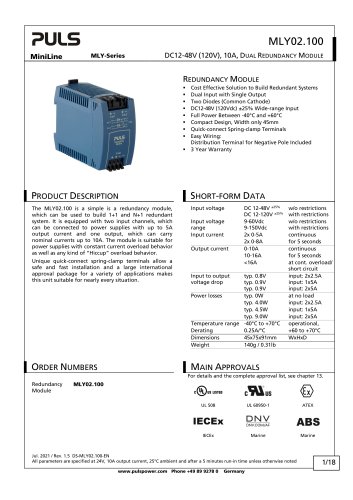 MLY02.100
18 Pages
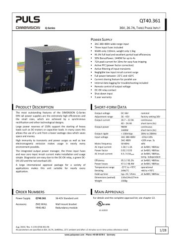 QT40.361
28 Pages
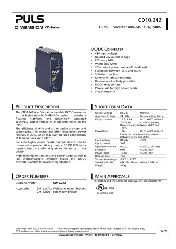 CD10.242
29 Pages
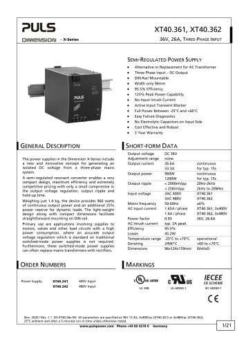 XT40.361, XT40.362
21 Pages
 SL20.310
2 Pages
 SL20.300
2 Pages
 ML70.100
2 Pages
 SLR01
SLR012 Pages
 SLR10.100
2 Pages
 SL40.301
2 Pages
 SL40.300
2 Pages
 SL30.300
2 Pages
 SL20.303
2 Pages
 SL20.301
2 Pages
 SL10.309
2 Pages
 SL10.305
4 Pages
 SL10.300
2 Pages
 SL5.300
2 Pages
 SL30.100
2 Pages
 SL20.115
2 Pages
 SL20.113
2 Pages
 SL20.112
2 Pages
 SL20.111
2 Pages
 SL20.110
2 Pages
 SL20.101
2 Pages
 SL20.100
2 Pages
 SL10.106
2 Pages
 SL10.105
2 Pages
 SL10.10
2 Pages
 SL10.104
2 Pages
 SL10.101
2 Pages
 SL10.100
2 Pages
 SL5.105
2 Pages
 SL5.102
2 Pages
 SL5.100
2 Pages
 SL4.100
2 Pages
 SL2.103
2 Pages
 SL2.100
2 Pages
 ML100.200
2 Pages
 ML90.200
2 Pages
 ML100.105
2 Pages
 ML100.102
2 Pages
 ML100.100
2 Pages
 ML95.100
2 Pages
 ML60.121
23 Pages
 ML50.111
2 Pages
 ML50.109
20 Pages
 ML50.105
2 Pages
 ML50.102
2 Pages
 ML50.101
2 Pages
 ML50.100
20 Pages
 ML30.241
23 Pages
 ML30.106
2 Pages
 ML30.102
2 Pages
 ML30.101
2 Pages
 ML30.100
2 Pages
 ML15.241
23 Pages
 ML15.121
23 Pages
 ML15.051
22 Pages
 YRM2.DIODE
19 Pages
 YR80.241
17 Pages
 YR40.241
17 Pages
 YR2.DIODE
19 Pages
 XT40.722
19 Pages
 XT40.721
19 Pages
 XT40.482
20 Pages
 XT40.481
20 Pages
 XT40.362
20 Pages
 XT40.242
20 Pages
 XT40.241
20 Pages
 ZM15.SIDE
2 Pages
 ZM14.SIDE
2 Pages
 ZM13.SIDE
2 Pages
 ZM12.SIDE
2 Pages
 ZM11.SIDE
2 Pages
 ZM2.WALL
3 Pages
 ZM1.WALL
2 Pages
 ZM1.UBC10
2 Pages
 UZS24.100
3 Pages
 UF20.481
13 Pages
 UZO12.26
2 Pages
 UZO12.07
9 Pages
 UZK12.261
8 Pages
 UZK12.071
9 Pages
 UBC10.241-N1
23 Pages
 UBC10.241
23 Pages
 UB10.245
24 Pages
 UB10.242
21 Pages
 UB10.241
23 Pages
 QT40.481
28 Pages
 QT40.241
28 Pages
 QT20.481
23 Pages
 QT20.361
23 Pages
 QT20.241-C1
23 Pages
 QT20.241
23 Pages
 QTD20.241
22 Pages
 QS10.481-D1
27 Pages
 QS10.241-D1
27 Pages
 QS40.484
28 Pages
 QS40.244
28 Pages
 QS20.481
25 Pages
 QS20.361
25 Pages
 QS20.244
25 Pages
 QS20.241-C1
26 Pages
 QS20.241-A1
26 Pages
 QS20.241
26 Pages
 QS10.481
27 Pages
 QS10.DNET
22 Pages
 QS10.301
26 Pages
 QS5.DNET
21 Pages
 QS5.241-A1
26 Pages
 QS5.241
26 Pages
 QS3.241
25 Pages
 PISA11.CLASS2
19 Pages
 PISA11.206212
23 Pages
 PISA11.203206
23 Pages
 PISA11.410
23 Pages
 PISA11.406
23 Pages
 PISA11.404
23 Pages
 PISA11.403
23 Pages
 PISA11.402
23 Pages
 PISA11.401
23 Pages
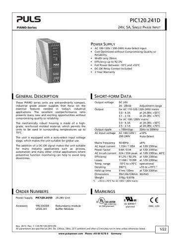
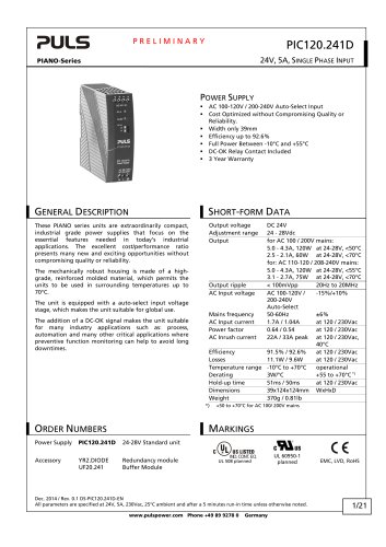
 PIC240.241D
21 Pages
 PIC120.241C
21 Pages
 PAS395
14 Pages
 CT10.481
22 Pages
 CT10.241
22 Pages
 CT5.241
21 Pages
 CT5.121
21 Pages
 CS10.481
20 Pages
 CS10.244
21 Pages
 CS10.243
19 Pages
 CS10.242
19 Pages
 CS10.241-S1
20 Pages
 CS10.241
20 Pages
 CS5.244
20 Pages
 CS5.243
19 Pages
 CS5.241-S1
20 Pages
 CS5.241-C1
20 Pages
 CS5.241
20 Pages
 CS3.241
21 Pages
 CPS20.241-C1
26 Pages
 CPS10.241
26 Pages
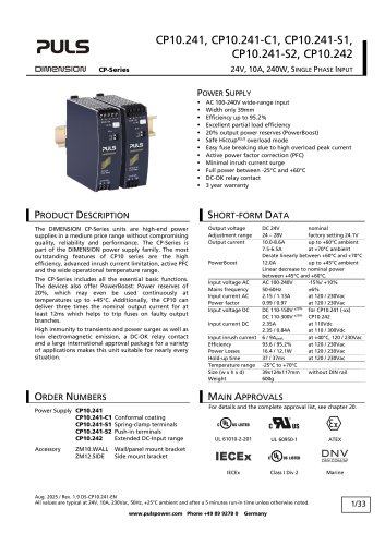
 CP10.242
27 Pages
 CD5.243
22 Pages
 CD5.242
22 Pages
 CD5.241-S1
23 Pages
 CD5.241-L1
21 Pages
 CD5.241
22 Pages
 CD5.121
22 Pages
 PIC120.242C
21 Pages
 PIC240.241C
20 Pages
 QS40.361
27 Pages
 QS40.481
28 Pages
 UB20.241
31 Pages
 UZK24.071
9 Pages
 UZK24.121
9 Pages
 UZO24.071
9 Pages
 UZO24.121
9 Pages
 UC10.241
27 Pages
 UC10.242
27 Pages
 YR40.242
17 Pages
 YR40.245
18 Pages

Archived catalogs
 SLZ02
SLZ022 Pages
 SLZ11
SLZ112 Pages
 SLZ12
SLZ122 Pages
 SLZ14
SLZ142 Pages
 FPS300 series
32 Pages
 FPT500 series
35 Pages
 QS10.121
26 Pages
 QS10.241
28 Pages
 QS10.241-A1
27 Pages
 QS10.241-C1
27 Pages
 Selection Guide 2015/2016
25 Pages
 selection guide 2018
31 Pages
 DECENTRALIZED POWER SUPPLIES
9 Pages
 PIANO PIC
2 Pages
 PULS CP
7 Pages
 YR40.482
17 Pages
 YR80.242
17 Pages
 SLA3.100
4 Pages
 SLA4.100
4 Pages
 SLA8.100
4 Pages
 SLA8.300
4 Pages
 SLAD4.100
4 Pages
 SLD2.100
2 Pages
 SLR02
SLR022 Pages
 SLR2.100
2 Pages
 SLR5.100
2 Pages
 SLR10.108
2 Pages
 SLV20.200
4 Pages
 SLZ10-14
2 Pages
 ML60.122
23 Pages
 ML60.241
23 Pages
 ML60.242
23 Pages
 ML120.241
22 Pages
 ML120.244
21 Pages
 ML120.CLASS2
19 Pages
 CP10.121
26 Pages
 PIANO
PIANO5 Pages
 ZM3.WALL
1 Page
 CPS20.481-D1
25 Pages
 CPS20.241-D1
25 Pages
 Selection Guide 2013
19 Pages
 QS40.241, QS40.241-A1
28 Pages
 CPS20.241
25 Pages
 CPS20.361
25 Pages
 CPS20.481
25 Pages
 CPS20.121
25 Pages
 PIC120.241D_2015
22 Pages
 PIC120.241D_2014
21 Pages
 Products 2009-2010
28 Pages
 Products 2007
34 Pages


- Lumibird DC power supply
- Lumibird AC/DC power supply
- CE power supply
- Single-output power supply
- Switching power supply
- Power supply for industrial applications
- Circuit breaker
- DC-DC converter
- Power supply with overload protection
- Compact power supply
- DIN rail power supply
- Variable-output power supply
- Single-phase power supply
- Multiple-output power supply
- Regulated power supply
- Industrial UPS
- Current circuit breaker
- Three-phase power supply
- Voltage circuit breaker