UC10.242
1 /27Pages

UC10.242
1 /27Pages
Catalog excerpts

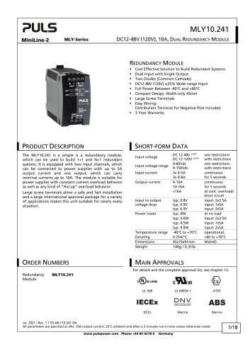
24V, 15A, CAPACITOR-BASED BUFFER MODULES CAPACITOR-BASED BUFFER MODULES Built-in Capacitors as Energy Source (EDLC Electrochemical Double Layer Capacitors) Wide Temperature Range from -40°C to +60°C Typically >10 Years Operational Lifetime Expectancy Regulated Output Voltage in Buffer Mode No Ventilated Cabinets Required (No Generation of Hydrogen as VRLA batteries do) Active Balancing for Longest Life and Buffer Times Short Charging Time, Unit is Rapidly Back in Ready Mode Output is Decoupled from the Input to Separate Load Circuits into Buffered and Non-buffered Sections Supports PC-Mode Function 3 Year Warranty GENERAL DESCRIPTION SHORT-FORM DATA The DIMENSION UC-Series are buffer modules utilizing Electrochemical Double Layer Capacitors (EDLC), commonly known as Ultracapacitors or Supercapacitors, which are installed inside the buffer module. They can bridge power failures or voltage fluctuations and supply voltage to the DC 24V bus for a certain period, which allows for a safe shut-down of the system. Expensive downtimes, long restart cycles and loss of data can be avoided. Nominal voltage Output current Buffer voltage Input current In times when the power supply provides sufficient voltages, the buffer module stores energy in the capacitors. In case of a mains voltage fault, this energy is released to the DC bus in a regulated process. The buffer modules are maintenance-free and have a similar lifetime expectancy as power supplies. No regular replacement of the capacitors is necessary as is required for battery based UPS systems. The wide temperature range from -40°C to +60°C makes the unit suitable for many applications. The buffer modules come in two versions which differ in the size of the installed capacitors. ORDER NUMBERS continuous fixed, 15A – 0A during charging, output current not included Capacitor size 6kWs UC10.241 12kWs UC10.242 Charging time 16 minutes UC10.241 32 minutes UC10.242 Buffer time 16.5s at 10A UC10.241 33s at 10A UC10.242 Power losses 4.6W in normal mode at 10A output current Temperature range -40°C to +60°C operational Dimensions 126x124x117mm UC10.241 WxHxD 198x124x117mm UC10.242 Weight 1150g / 2.54lb UC10.241 1720g / 3.79lb UC10.242 6kWs energy source 12kWs energy source Wall-mount bracket Apr. 2014 / Rev. 2.0 DS-UC10.241-EN (REVC) All parameters are specified at 24V, 10A output current, 25°C ambient and after a 5 minutes run-in time unless otherwise noted. www.pulspower.com Phone +49 89 9278 0
Open the catalog to page 1
The information presented in this document is believed to be accurate and reliable and may change without notice. No part of this document may be reproduced or utilized in any form without permission in writing from the publisher. TERMINOLOGY AND ABREVIATIONS Buffer Module Short term buffer system with DC-In-/Output. Utilizes capacitors as energy source Uninterruptible power supply system with DC-In-/Output. Utilizes batteries as energy source Normal mode Describes a condition where the capacitor is charged, the input voltage is in range and the output is loaded within the allowed limits. Buffer...
Open the catalog to page 2
1. INTENDED USE This device is designed for installation in an enclosure. Use an appropriate enclosure which protects against mechanical, electrical and fire hazards. This device is intended for professional use in areas such as in industrial control, office, communication, and instrumentation equipment. Do not use this device in equipment or systems where malfunction may cause severe personal injury or threaten human life. 2. INSTALLATION NOTES This device may only be installed and put into operation by qualified personnel. This device does not contain serviceable parts. The tripping of an internal...
Open the catalog to page 3
3. INPUT Input voltage Input voltage ranges Transfer threshold voltage Turn-on voltage Allowed voltage between input and earth (chassis) Current consumption Input current Return current continuous operation temporarily allowed, no damage to the unit Between 30 and 35Vdc buffering is not possible, the unit indicates “Check Input Voltage” with the red LED on the front at no load at 10A buffer current at 15A buffer current at 15A buffer current The transfer threshold voltage describes the input voltage, where the unit switches into buffer mode and delivers output voltage from the capacitors if the...
Open the catalog to page 4
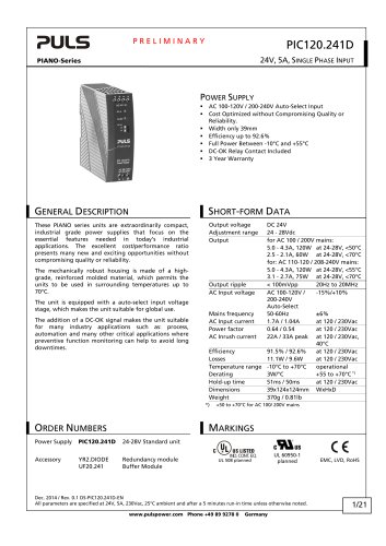
□IfinenJSIOflJ UC-Series 24V, 15A, CAPACITOR-BASED BUFFER MODULES The output section of the buffer module is fully controlled and is equipped with an electronic current limitation. A current overloading of the buffer module cannot happen, independent of which sizes of power supplies are used on the input of the buffer module. The current limitation works in a switching mode which reduces the power losses and heat generation to a minimum. Output in normal mode: In normal mode (and also in charging mode), the output voltage is slightly lower as the input voltage. The output voltage follows the...
Open the catalog to page 5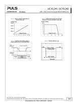
Fig. 4-2 Output characteristic and overload behavior in normal and buffer mode, typ. Fig. 4-1 Input to output voltage drop in normal mode, typ. Output Voltage Voltage drop Output Current Output Current Fig. 4-3 Transition from buffer mode to normal mode and vice versa, definitions Input voltage Output Voltage t Output voltage 24V Normal mode Buffer mode Normal mode Input Voltage Apr. 2014 / Rev. 2.0 DS-UC10.241-EN (REVC) All parameters are specified at 24V, 10A output current, 25°C ambient and after a 5 minutes run-in time unless otherwise noted. www.pulspower.com Phone +49 89 9278 0
Open the catalog to page 6
5. CHARGING During charging, the buffer module consumes additional current from the input. See chapter “Input”. When charging is completed, the “Ready LED” stops flashing and is on solid and the “Ready relay contact” closes. UC10.241 16 minutes when capacitor is completely discharged after discharging with 10A for 10s typ. Allowed number of charging / discharging cycles Charging time initial charging*) Charging time recharging**) after discharging with 10A until buffering stops after discharging with 5A until buffering stops after discharging with 1A until buffering stops Initial charging means...
Open the catalog to page 7All PULS GmbH catalogs and technical brochures
 MLY10.241
18 Pages
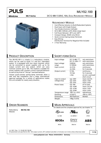 MLY02.100
18 Pages
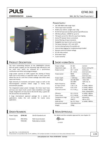 QT40.361
28 Pages
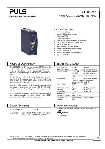 CD10.242
29 Pages
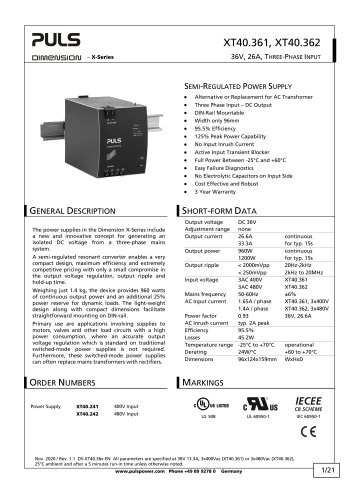 XT40.361, XT40.362
21 Pages
 SL20.310
2 Pages
 SL20.300
2 Pages
 ML70.100
2 Pages
 SLR01
SLR012 Pages
 SLR10.100
2 Pages
 SL40.301
2 Pages
 SL40.300
2 Pages
 SL30.300
2 Pages
 SL20.303
2 Pages
 SL20.301
2 Pages
 SL10.309
2 Pages
 SL10.305
4 Pages
 SL10.300
2 Pages
 SL5.300
2 Pages
 SL30.100
2 Pages
 SL20.115
2 Pages
 SL20.113
2 Pages
 SL20.112
2 Pages
 SL20.111
2 Pages
 SL20.110
2 Pages
 SL20.101
2 Pages
 SL20.100
2 Pages
 SL10.106
2 Pages
 SL10.105
2 Pages
 SL10.10
2 Pages
 SL10.104
2 Pages
 SL10.101
2 Pages
 SL10.100
2 Pages
 SL5.105
2 Pages
 SL5.102
2 Pages
 SL5.100
2 Pages
 SL4.100
2 Pages
 SL2.103
2 Pages
 SL2.100
2 Pages
 ML100.200
2 Pages
 ML90.200
2 Pages
 ML100.105
2 Pages
 ML100.102
2 Pages
 ML100.100
2 Pages
 ML95.100
2 Pages
 ML60.121
23 Pages
 ML50.111
2 Pages
 ML50.109
20 Pages
 ML50.105
2 Pages
 ML50.102
2 Pages
 ML50.101
2 Pages
 ML50.100
20 Pages
 ML30.241
23 Pages
 ML30.106
2 Pages
 ML30.102
2 Pages
 ML30.101
2 Pages
 ML30.100
2 Pages
 ML15.241
23 Pages
 ML15.121
23 Pages
 ML15.051
22 Pages
 YRM2.DIODE
19 Pages
 YR80.241
17 Pages
 YR40.241
17 Pages
 YR2.DIODE
19 Pages
 XT40.722
19 Pages
 XT40.721
19 Pages
 XT40.482
20 Pages
 XT40.481
20 Pages
 XT40.362
20 Pages
 XT40.242
20 Pages
 XT40.241
20 Pages
 ZM15.SIDE
2 Pages
 ZM14.SIDE
2 Pages
 ZM13.SIDE
2 Pages
 ZM12.SIDE
2 Pages
 ZM11.SIDE
2 Pages
 ZM2.WALL
3 Pages
 ZM1.WALL
2 Pages
 ZM1.UBC10
2 Pages
 UZS24.100
3 Pages
 UF20.481
13 Pages
 UF20.241
11 Pages
 UZO12.26
2 Pages
 UZO12.07
9 Pages
 UZK12.261
8 Pages
 UZK12.071
9 Pages
 UBC10.241-N1
23 Pages
 UBC10.241
23 Pages
 UB10.245
24 Pages
 UB10.242
21 Pages
 UB10.241
23 Pages
 QT40.481
28 Pages
 QT40.241
28 Pages
 QT20.481
23 Pages
 QT20.361
23 Pages
 QT20.241-C1
23 Pages
 QT20.241
23 Pages
 QTD20.241
22 Pages
 QS10.481-D1
27 Pages
 QS10.241-D1
27 Pages
 QS40.484
28 Pages
 QS40.244
28 Pages
 QS20.481
25 Pages
 QS20.361
25 Pages
 QS20.244
25 Pages
 QS20.241-C1
26 Pages
 QS20.241-A1
26 Pages
 QS20.241
26 Pages
 QS10.481
27 Pages
 QS10.DNET
22 Pages
 QS10.301
26 Pages
 QS5.DNET
21 Pages
 QS5.241-A1
26 Pages
 QS5.241
26 Pages
 QS3.241
25 Pages
 PISA11.CLASS2
19 Pages
 PISA11.206212
23 Pages
 PISA11.203206
23 Pages
 PISA11.410
23 Pages
 PISA11.406
23 Pages
 PISA11.404
23 Pages
 PISA11.403
23 Pages
 PISA11.402
23 Pages
 PISA11.401
23 Pages
 PIC240.241D
21 Pages
 PIC120.241C
21 Pages
 PAS395
14 Pages
 CT10.481
22 Pages
 CT10.241
22 Pages
 CT5.241
21 Pages
 CT5.121
21 Pages
 CS10.481
20 Pages
 CS10.244
21 Pages
 CS10.243
19 Pages
 CS10.242
19 Pages
 CS10.241-S1
20 Pages
 CS10.241
20 Pages
 CS5.244
20 Pages
 CS5.243
19 Pages
 CS5.241-S1
20 Pages
 CS5.241-C1
20 Pages
 CS5.241
20 Pages
 CS3.241
21 Pages
 CPS20.241-C1
26 Pages
 CPS10.241
26 Pages
 CP10.242
27 Pages
 CD5.243
22 Pages
 CD5.242
22 Pages
 CD5.241-S1
23 Pages
 CD5.241-L1
21 Pages
 CD5.241
22 Pages
 CD5.121
22 Pages
 PIC120.242C
21 Pages
 PIC240.241C
20 Pages
 QS40.361
27 Pages
 QS40.481
28 Pages
 UB20.241
31 Pages
 UZK24.071
9 Pages
 UZK24.121
9 Pages
 UZO24.071
9 Pages
 UZO24.121
9 Pages
 UC10.241
27 Pages
 YR40.242
17 Pages
 YR40.245
18 Pages

Archived catalogs
 SLZ02
SLZ022 Pages
 SLZ11
SLZ112 Pages
 SLZ12
SLZ122 Pages
 SLZ14
SLZ142 Pages
 FPS300 series
32 Pages
 FPT500 series
35 Pages
 QS10.121
26 Pages
 QS10.241
28 Pages
 QS10.241-A1
27 Pages
 QS10.241-C1
27 Pages
 Selection Guide 2015/2016
25 Pages
 selection guide 2018
31 Pages
 DECENTRALIZED POWER SUPPLIES
9 Pages
 PIANO PIC
2 Pages
 PULS CP
7 Pages
 YR40.482
17 Pages
 YR80.242
17 Pages
 SLA3.100
4 Pages
 SLA4.100
4 Pages
 SLA8.100
4 Pages
 SLA8.300
4 Pages
 SLAD4.100
4 Pages
 SLD2.100
2 Pages
 SLR02
SLR022 Pages
 SLR2.100
2 Pages
 SLR5.100
2 Pages
 SLR10.108
2 Pages
 SLV20.200
4 Pages
 SLZ10-14
2 Pages
 ML60.122
23 Pages
 ML60.241
23 Pages
 ML60.242
23 Pages
 ML120.241
22 Pages
 ML120.244
21 Pages
 ML120.CLASS2
19 Pages
 CP10.121
26 Pages
 PIANO
PIANO5 Pages
 ZM3.WALL
1 Page
 CPS20.481-D1
25 Pages
 CPS20.241-D1
25 Pages
 Selection Guide 2013
19 Pages
 QS40.241, QS40.241-A1
28 Pages
 CPS20.241
25 Pages
 CPS20.361
25 Pages
 CPS20.481
25 Pages
 CPS20.121
25 Pages
 PIC120.241D_2015
22 Pages
 PIC120.241D_2014
21 Pages
 Products 2009-2010
28 Pages
 Products 2007
34 Pages


- DC power supply
- AC/DC power supply
- CE power supply
- Single-output power supply
- Switching power supply
- Power supply for industrial applications
- DC-DC converter
- Circuit breaker
- Power supply with overload protection
- Compact power supply
- DIN rail power supply
- Variable-output power supply
- Single-phase power supply
- Multiple-output power supply
- Regulated power supply
- Industrial UPS
- Three-phase power supply
- Current circuit breaker
- Voltage circuit breaker