UB20.241
1 /31Pages

UB20.241
1 /31Pages
Catalog excerpts
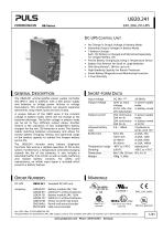
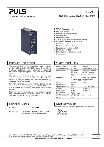
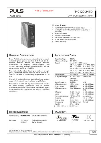
DC-UPS CONTROL UNIT No Change in Output Voltage in Battery Mode Selectable Output Voltages in Battery Mode 1-Battery-Concept Each 12V Battery is Charged and Monitored Separately for Longest Battery Life Precise Battery Charging by Using a Temperature Sensor Battery Size Selector for Small or Large Batteries 50% BonusPower®, 30A for up to 4s High Breaking Capacity for Branch Protectors Smart Battery Diagnostics and Monitoring Functions 3 Year Warranty GENERAL DESCRIPTION SHORT-FORM DATA The UB20.241 uninterruptible power supply controller (DC-UPS) is used in addition with a 24V power supply and batteries to bridge power failures or voltage fluctuations. This configuration can prevent expensive downtimes, long restart cycles and loss of data. Input voltage Output voltage A unique feature of the UB20 series is the constant voltage in battery mode, which will not change as the batteries discharge. The buffer voltage in battery mode can be set to four different output values. Another feature is the utilization of two independent battery chargers for the two 12V-batteries in series. This feature makes matching batteries unnecessary and allows for precise battery charging, testing and optimized usage of the battery capacity to achieve the longest battery service life. Output current The UB20.241 includes many battery diagnostic functions that ensure a reliable operation of the entire system. Furthermore, a temperature controlled charging extends the life of the batteries. It also includes a selectable buffer time limiter as well as ready, buffering and replace battery contacts. For safety and maintenance, an inhibit input signal is included which prevents a battery backup. ORDER NUMBERS 18-30Vdc in power supply mode in battery mode Allowed battery sizes Buffer time Temperature range Derating Dimensions Weight Standard DC-UPS unit Battery module 24V, 7Ah UZK24.071 without batteries Battery module 24V, 12Ah UZK24.121 without batteries Sensor & center tap board Panel/ wall-mount bracket Side-mount bracket IECEx Class I Div 2 planned Marine, planned Jan. 2015 / Rev. 2.0 DS-UB20.241-EN All parameters are specified at 24V, 20A output current, 25°C ambient and after a 5 minutes run-in time unless otherwise noted. www.pulspower.com Phone +49 89 9278 0
Open the catalog to page 1
The information presented in this document is believed to be accurate and reliable and may change without notice. No part of this document may be reproduced or utilized in any form without permission in writing from the publisher. Jan. 2015 / Rev. 2.0 DS-UB20.241-EN All parameters are specified at 24V, 20A output current, 25°C ambient and after a 5 minutes run-in time unless otherwise noted. www.pulspower.com Phone +49 89 9278 0
Open the catalog to page 2
1. TERMINOLOGY AND ABBREVIATIONS DC-UPS Abbreviation for Uninterruptible Power Supply system with a DC input and a DC output. A DC-UPS utilizes batteries as back-up energy source. Power supply mode Describes a condition where the input voltage is in the rated input voltage range and the supplying power supply can deliver a sufficient amount of current for the DC-UPS and the load. Additionally it is assumed that the output is loaded within the allowed limits and the battery is charged, if necessary. The mode can also be called “Normal mode”. Battery mode Describes a condition where the input voltage...
Open the catalog to page 3
2. INTENDED USE This device is designed for installation in an enclosure. Use an appropriate enclosure which protects against mechanical, electrical and fire hazards. This device is intended for professional use in areas such as in industrial control, office, communication, and instrumentation equipment. Do not use this device in equipment or systems where malfunction may cause severe personal injury or threaten human life. 3. INSTALLATION NOTES This device may only be installed and put into operation by qualified personnel. The input must be powered from a SELV or PELV power source. Use DIN-rails...
Open the catalog to page 4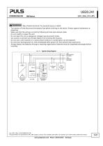
Risk of electrical shock, fire, personal injury or death. - Turn power off and disconnect the battery fuse before working on the device. Protect against inadvertent repowering. - Make sure that the wiring is correct by following all local and national codes. - Do not modify or repair the unit. - Do not open the unit as dangerous voltages may be present inside. - Use caution to prevent any foreign objects from entering the housing. - Do not use in wet locations or in areas where moisture or condensation can be expected. - Do not touch during power-on, and immediately after power-off. Hot surfaces...
Open the catalog to page 5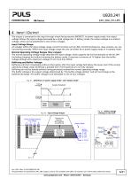
4. INPUT / OUTPUT The output is connected to the input through a back-fed protection (MOSFET). In power supply mode, the output voltage follows the input voltage decreased by a small voltage loss. In battery mode, the output voltage is a constant voltage, which can be preselected in one of four voltages. Input Voltage Range: At voltages within the input voltage range, control functions such as LEDs, monitoring features, relay contacts, etc. are functioning normally. Within the input voltage range the unit can either be in power supply mode or in battery mode. Normal Operating Voltage Ranges (four...
Open the catalog to page 6
Input voltage Input voltage range Control functions such as LEDs, monitoring features, relay contacts, etc. are working. The unit can either be in power supply mode or in battery mode. See Fig. 4-2. Temporarily allowed, no damage to the DC-UPS. The red error LED will report “Input Voltage”, charging and buffering are not possible. See Fig. 4-2. Absolute max. voltage with no damage to the unit. Ranges, where the unit does not switch to battery mode. See Fig. 4-2. Range A for a 22.5V buffer voltage setting Range B for a 24V buffer voltage setting Range C for a 25V buffer voltage setting Range D...
Open the catalog to page 7
Output current in power supply mode in battery mode typ. Overload behavior in power supply mode in battery mode Output short circuit current in power supply mode in battery mode Return current Allowed voltage between input and earth (chassis) Capacitive and inductive loads 1) 2) 3) Continuously allowed For max. 5s Continuously allowed see Fig. 4-7 (interpolate linearly between 22.5V and 26V) For typ. 4s (BonusPower® 4)) see Fig. 4-7 (interpolate linearly between 22.5V and 26V) For typ. 25ms, output voltage stays above 20V, (dynamic peak current), see Fig. 4-9. Description see footnotes 1) and...
Open the catalog to page 8All PULS GmbH catalogs and technical brochures
 MLY10.241
18 Pages
 MLY02.100
18 Pages
 QT40.361
28 Pages
 CD10.242
29 Pages
 XT40.361, XT40.362
21 Pages
 SL20.310
2 Pages
 SL20.300
2 Pages
 ML70.100
2 Pages
 SLR01
SLR012 Pages
 SLR10.100
2 Pages
 SL40.301
2 Pages
 SL40.300
2 Pages
 SL30.300
2 Pages
 SL20.303
2 Pages
 SL20.301
2 Pages
 SL10.309
2 Pages
 SL10.305
4 Pages
 SL10.300
2 Pages
 SL5.300
2 Pages
 SL30.100
2 Pages
 SL20.115
2 Pages
 SL20.113
2 Pages
 SL20.112
2 Pages
 SL20.111
2 Pages
 SL20.110
2 Pages
 SL20.101
2 Pages
 SL20.100
2 Pages
 SL10.106
2 Pages
 SL10.105
2 Pages
 SL10.10
2 Pages
 SL10.104
2 Pages
 SL10.101
2 Pages
 SL10.100
2 Pages
 SL5.105
2 Pages
 SL5.102
2 Pages
 SL5.100
2 Pages
 SL4.100
2 Pages
 SL2.103
2 Pages
 SL2.100
2 Pages
 ML100.200
2 Pages
 ML90.200
2 Pages
 ML100.105
2 Pages
 ML100.102
2 Pages
 ML100.100
2 Pages
 ML95.100
2 Pages
 ML60.121
23 Pages
 ML50.111
2 Pages
 ML50.109
20 Pages
 ML50.105
2 Pages
 ML50.102
2 Pages
 ML50.101
2 Pages
 ML50.100
20 Pages
 ML30.241
23 Pages
 ML30.106
2 Pages
 ML30.102
2 Pages
 ML30.101
2 Pages
 ML30.100
2 Pages
 ML15.241
23 Pages
 ML15.121
23 Pages
 ML15.051
22 Pages
 YRM2.DIODE
19 Pages
 YR80.241
17 Pages
 YR40.241
17 Pages
 YR2.DIODE
19 Pages
 XT40.722
19 Pages
 XT40.721
19 Pages
 XT40.482
20 Pages
 XT40.481
20 Pages
 XT40.362
20 Pages
 XT40.242
20 Pages
 XT40.241
20 Pages
 ZM15.SIDE
2 Pages
 ZM14.SIDE
2 Pages
 ZM13.SIDE
2 Pages
 ZM12.SIDE
2 Pages
 ZM11.SIDE
2 Pages
 ZM2.WALL
3 Pages
 ZM1.WALL
2 Pages
 ZM1.UBC10
2 Pages
 UZS24.100
3 Pages
 UF20.481
13 Pages
 UF20.241
11 Pages
 UZO12.26
2 Pages
 UZO12.07
9 Pages
 UZK12.261
8 Pages
 UZK12.071
9 Pages
 UBC10.241-N1
23 Pages
 UBC10.241
23 Pages
 UB10.245
24 Pages
 UB10.242
21 Pages
 UB10.241
23 Pages
 QT40.481
28 Pages
 QT40.241
28 Pages
 QT20.481
23 Pages
 QT20.361
23 Pages
 QT20.241-C1
23 Pages
 QT20.241
23 Pages
 QTD20.241
22 Pages
 QS10.481-D1
27 Pages
 QS10.241-D1
27 Pages
 QS40.484
28 Pages
 QS40.244
28 Pages
 QS20.481
25 Pages
 QS20.361
25 Pages
 QS20.244
25 Pages
 QS20.241-C1
26 Pages
 QS20.241-A1
26 Pages
 QS20.241
26 Pages
 QS10.481
27 Pages
 QS10.DNET
22 Pages
 QS10.301
26 Pages
 QS5.DNET
21 Pages
 QS5.241-A1
26 Pages
 QS5.241
26 Pages
 QS3.241
25 Pages
 PISA11.CLASS2
19 Pages
 PISA11.206212
23 Pages
 PISA11.203206
23 Pages
 PISA11.410
23 Pages
 PISA11.406
23 Pages
 PISA11.404
23 Pages
 PISA11.403
23 Pages
 PISA11.402
23 Pages
 PISA11.401
23 Pages
 PIC240.241D
21 Pages
 PIC120.241C
21 Pages
 PAS395
14 Pages
 CT10.481
22 Pages
 CT10.241
22 Pages
 CT5.241
21 Pages
 CT5.121
21 Pages
 CS10.481
20 Pages
 CS10.244
21 Pages
 CS10.243
19 Pages
 CS10.242
19 Pages
 CS10.241-S1
20 Pages
 CS10.241
20 Pages
 CS5.244
20 Pages
 CS5.243
19 Pages
 CS5.241-S1
20 Pages
 CS5.241-C1
20 Pages
 CS5.241
20 Pages
 CS3.241
21 Pages
 CPS20.241-C1
26 Pages
 CPS10.241
26 Pages
 CP10.242
27 Pages
 CD5.243
22 Pages
 CD5.242
22 Pages
 CD5.241-S1
23 Pages
 CD5.241-L1
21 Pages
 CD5.241
22 Pages
 CD5.121
22 Pages
 PIC120.242C
21 Pages
 PIC240.241C
20 Pages
 QS40.361
27 Pages
 QS40.481
28 Pages
 UZK24.071
9 Pages
 UZK24.121
9 Pages
 UZO24.071
9 Pages
 UZO24.121
9 Pages
 UC10.241
27 Pages
 UC10.242
27 Pages
 YR40.242
17 Pages
 YR40.245
18 Pages

Archived catalogs
 SLZ02
SLZ022 Pages
 SLZ11
SLZ112 Pages
 SLZ12
SLZ122 Pages
 SLZ14
SLZ142 Pages
 FPS300 series
32 Pages
 FPT500 series
35 Pages
 QS10.121
26 Pages
 QS10.241
28 Pages
 QS10.241-A1
27 Pages
 QS10.241-C1
27 Pages
 Selection Guide 2015/2016
25 Pages
 selection guide 2018
31 Pages
 DECENTRALIZED POWER SUPPLIES
9 Pages
 PIANO PIC
2 Pages
 PULS CP
7 Pages
 YR40.482
17 Pages
 YR80.242
17 Pages
 SLA3.100
4 Pages
 SLA4.100
4 Pages
 SLA8.100
4 Pages
 SLA8.300
4 Pages
 SLAD4.100
4 Pages
 SLD2.100
2 Pages
 SLR02
SLR022 Pages
 SLR2.100
2 Pages
 SLR5.100
2 Pages
 SLR10.108
2 Pages
 SLV20.200
4 Pages
 SLZ10-14
2 Pages
 ML60.122
23 Pages
 ML60.241
23 Pages
 ML60.242
23 Pages
 ML120.241
22 Pages
 ML120.244
21 Pages
 ML120.CLASS2
19 Pages
 CP10.121
26 Pages
 PIANO
PIANO5 Pages
 ZM3.WALL
1 Page
 CPS20.481-D1
25 Pages
 CPS20.241-D1
25 Pages
 Selection Guide 2013
19 Pages
 QS40.241, QS40.241-A1
28 Pages
 CPS20.241
25 Pages
 CPS20.361
25 Pages
 CPS20.481
25 Pages
 CPS20.121
25 Pages
 PIC120.241D_2015
22 Pages
 PIC120.241D_2014
21 Pages
 Products 2009-2010
28 Pages
 Products 2007
34 Pages


- DC power supply
- AC/DC power supply
- CE power supply
- Single-output power supply
- Switching power supply
- Power supply for industrial applications
- DC-DC converter
- Circuit breaker
- Power supply with overload protection
- Compact power supply
- DIN rail power supply
- Variable-output power supply
- Single-phase power supply
- Multiple-output power supply
- Regulated power supply
- Industrial UPS
- Three-phase power supply
- Current circuit breaker
- Voltage circuit breaker