PAS395
1 /14Pages

PAS395
1 /14Pages
Catalog excerpts
Charger for EDLC Capacitors (Ultra-Caps) Prepared: Michael Raspotnig, PULS GmbH 2013/01/19 2 Typical Wiring Scheme 3 8 LEDs and Relay Contacts Pattern 8 10 Dielectric Strength, Isolation, Leakage Current 9 This document is proprietary. Any dispatch or disclosure of content is authorized only after written authorization by PULS GmbH. All parameters are specified at 400V, 2.5A, 230Vac, 25°C ambient and after a 5 minutes run-in time unless otherwise noted.
Open the catalog to page 1
Functional Description - The charger is designed to charge EDLC (electrical double layer capacitors commonly known as Ultracaps, Supercaps or Greencaps) with a constant current – constant voltage characteristic (float charge mode). The charger is suitable to be used in a permanently spinning rotor-hub of a wind turbine. The charger is suitable for flange mounting. Any mounting orientation is allowed. Most of the heat will be conducted through the base-plate of the charger. A good thermal connection to the cabinet or an external heatsink can improve the MTBF and life time expectancy. The charger...
Open the catalog to page 2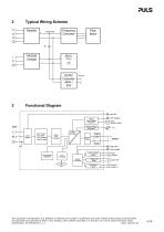
Typical Wiring Scheme Functional Diagram Input Fuses Input Filter Input Rectifier Inrush Limiter Over Voltage Output Voltage disable/ enable Fully charged This document is proprietary. Any dispatch or disclosure of content is authorized only after written authorization by PULS GmbH. All parameters are specified at 400V, 2.5A, 230Vac, 25°C ambient and after a 5 minutes run-in time unless otherwise noted.
Open the catalog to page 3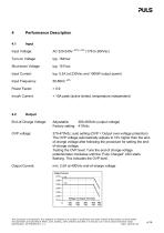
Performance Description Input Voltage: Turn-on Voltage Shut-down Voltage Input Current: Input Frequency: Power Factor: Inrush Current: < 10A peak (active limited, temperature independent) End-of-Charge Voltage: Adjustable: 360-460Vdc (output voltage) Factory setting: 410Vdc 370-470Vdc; auto setting (OVP = Output over-voltage protection) The OVP voltage automatically adjusts to 10V higher then the endof-charge voltage after following the procedure for setting the endof-charge voltage. Testing the OVP level: Tune the end-of charge-voltage potentiometer clockwise until the “Fully Charged” LED starts...
Open the catalog to page 4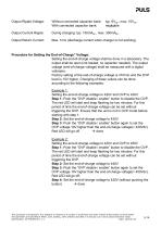
Output Ripple-Voltage: Without connected capacitor bank: With connected capacitor bank: Output Current Ripple: Output Return Current: Max. 1mA (discharge current when charger is not working) Procedure for Setting the End-of-Charge” Voltage: Setting the end-of-charge voltage shall be done in a laboratory. The output shall be open (not loaded, no capacitor needed). The output voltage (end-of-charge voltage) shall be measured with a digital voltmeter. Factory setting of the end-of-charge voltage is 410Vdc and the OVP level is 10V higher. Changing of these values can be done according to the following...
Open the catalog to page 5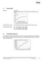
General Data at 400Vdc output voltage, 2.6A output current and 230Vac input Full-load Power Losses: typ. 60.8W at 400Vdc output voltage and 2.6A output current No-load Power Losses: The charger is suitable to charge capacitors up to 5F. The typical capacitance is considered to be 2F. Therefore, most of the following curves and investigations apply for this size of capacitor unless otherwise stated. Voltage on Output Terminals for a 2F EDLC, typ This document is proprietary. Any dispatch or disclosure of content is authorized only after written authorization by PULS GmbH. All parameters are specified...
Open the catalog to page 6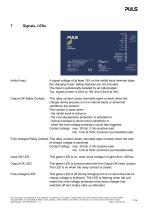
/j\ Installation by professional personnel « ' Do not use without protective earth ADo not open, risk of electrical shock Read PAS395 instruction manual Assembled in Czech Republic Factory settings: Electronically protected End-of -Charge Voltage o Signals, LEDs Inhibit Input: A signal voltage of at least 18V on the inhibit input terminal stops the charging mode. Safety features are not included. The input is galvanically isolated by an optocoupler. Output-OK Relay Contact: This relay contact closes (normally-open-contact) when the charger works properly and no internal faults or abnormal The...
Open the catalog to page 7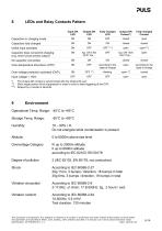
8 LEDs and Relay Contacts Pattern Input-OK Output-OK Fully charged Output OK Fully charged Capacitors in charging mode ON ON OFF closed open Capacitors fully charged ON ON ON closed closed Inhibit input activated ON OFF OFF***) open open***) Capacitor does not permit charging ON typ. ON 130s OFF typ. ON 130s open (e.g. short circuit across output) OFFHOs... OFFHOs... No capacitor connected ON ON ON closed closed Over-temperature shut-down (OTP) ON OFF according to the open according to the state-of-charge state of charge Over-voltage protection activated (OVP) ON OFF **) flashing open **) closed...
Open the catalog to page 8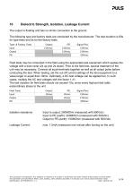
Dielectric Strength, Isolation, Leakage Current The output is floating and has no ohmic connection to the ground. The following type and factory tests are conducted by the manufacturer. The test duration is 60s for type tests and 5s for the factory tests. Type- & Factory Tests Input Signal Pins Field tests may be conducted in the field using the appropriate test equipment which applies the voltage with a slow ramp (2s up and 2s down). Prior to the field test, special treatment of the unit may be necessary. Connect all input-terminals together as well as all output poles before conducting the...
Open the catalog to page 9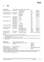
Electrostatic discharge Contact discharge Air discharge Fast transients (Burst) Input lines Output lines Signal lines Criterion A Criterion A Criterion A Surge voltage on input Surge voltage on signals Conducted disturbance Mains voltage dips Criterion A Criterion C *) Criterion A Voltage interruptions Powerful transients over entire load range Surge voltage on output Criterions: A: Power supply shows normal operation behavior within the defined limits. C: Temporary loss of function is possible. Power supply may shut-down and restarts by itself. No damage or hazards for the power supply will...
Open the catalog to page 10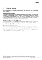
Protection Features The output is short-circuit, overload and no-load proof. After removing the fault, an auto-restart will be performed. Over- temperature protection: A temperature sensor monitors the internal temperature of a semiconductor. If the temperature rises above a certain level, the fan will be turned on. If the temperature keeps rising, the output will switch off in order to protect the charger. The output will automatically turn on again as soon as the temperature decreases by 5°C. The “Output-OK” LED will be off and the “Output-OK” contact will be open when the over-temperature...
Open the catalog to page 11All PULS GmbH catalogs and technical brochures
 MLY10.241
18 Pages
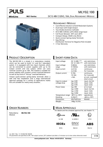 MLY02.100
18 Pages
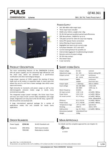 QT40.361
28 Pages
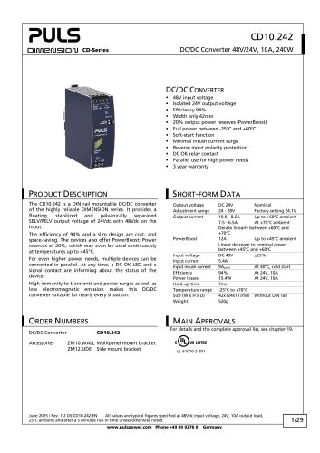 CD10.242
29 Pages
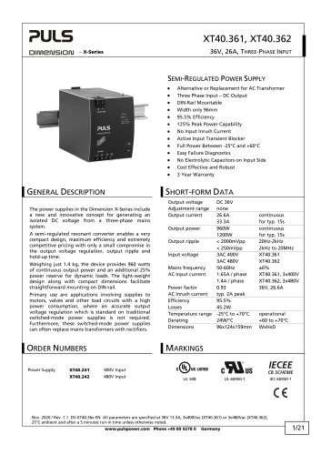 XT40.361, XT40.362
21 Pages
 SL20.310
2 Pages
 SL20.300
2 Pages
 ML70.100
2 Pages
 SLR01
SLR012 Pages
 SLR10.100
2 Pages
 SL40.301
2 Pages
 SL40.300
2 Pages
 SL30.300
2 Pages
 SL20.303
2 Pages
 SL20.301
2 Pages
 SL10.309
2 Pages
 SL10.305
4 Pages
 SL10.300
2 Pages
 SL5.300
2 Pages
 SL30.100
2 Pages
 SL20.115
2 Pages
 SL20.113
2 Pages
 SL20.112
2 Pages
 SL20.111
2 Pages
 SL20.110
2 Pages
 SL20.101
2 Pages
 SL20.100
2 Pages
 SL10.106
2 Pages
 SL10.105
2 Pages
 SL10.10
2 Pages
 SL10.104
2 Pages
 SL10.101
2 Pages
 SL10.100
2 Pages
 SL5.105
2 Pages
 SL5.102
2 Pages
 SL5.100
2 Pages
 SL4.100
2 Pages
 SL2.103
2 Pages
 SL2.100
2 Pages
 ML100.200
2 Pages
 ML90.200
2 Pages
 ML100.105
2 Pages
 ML100.102
2 Pages
 ML100.100
2 Pages
 ML95.100
2 Pages
 ML60.121
23 Pages
 ML50.111
2 Pages
 ML50.109
20 Pages
 ML50.105
2 Pages
 ML50.102
2 Pages
 ML50.101
2 Pages
 ML50.100
20 Pages
 ML30.241
23 Pages
 ML30.106
2 Pages
 ML30.102
2 Pages
 ML30.101
2 Pages
 ML30.100
2 Pages
 ML15.241
23 Pages
 ML15.121
23 Pages
 ML15.051
22 Pages
 YRM2.DIODE
19 Pages
 YR80.241
17 Pages
 YR40.241
17 Pages
 YR2.DIODE
19 Pages
 XT40.722
19 Pages
 XT40.721
19 Pages
 XT40.482
20 Pages
 XT40.481
20 Pages
 XT40.362
20 Pages
 XT40.242
20 Pages
 XT40.241
20 Pages
 ZM15.SIDE
2 Pages
 ZM14.SIDE
2 Pages
 ZM13.SIDE
2 Pages
 ZM12.SIDE
2 Pages
 ZM11.SIDE
2 Pages
 ZM2.WALL
3 Pages
 ZM1.WALL
2 Pages
 ZM1.UBC10
2 Pages
 UZS24.100
3 Pages
 UF20.481
13 Pages
 UF20.241
11 Pages
 UZO12.26
2 Pages
 UZO12.07
9 Pages
 UZK12.261
8 Pages
 UZK12.071
9 Pages
 UBC10.241-N1
23 Pages
 UBC10.241
23 Pages
 UB10.245
24 Pages
 UB10.242
21 Pages
 UB10.241
23 Pages
 QT40.481
28 Pages
 QT40.241
28 Pages
 QT20.481
23 Pages
 QT20.361
23 Pages
 QT20.241-C1
23 Pages
 QT20.241
23 Pages
 QTD20.241
22 Pages
 QS10.481-D1
27 Pages
 QS10.241-D1
27 Pages
 QS40.484
28 Pages
 QS40.244
28 Pages
 QS20.481
25 Pages
 QS20.361
25 Pages
 QS20.244
25 Pages
 QS20.241-C1
26 Pages
 QS20.241-A1
26 Pages
 QS20.241
26 Pages
 QS10.481
27 Pages
 QS10.DNET
22 Pages
 QS10.301
26 Pages
 QS5.DNET
21 Pages
 QS5.241-A1
26 Pages
 QS5.241
26 Pages
 QS3.241
25 Pages
 PISA11.CLASS2
19 Pages
 PISA11.206212
23 Pages
 PISA11.203206
23 Pages
 PISA11.410
23 Pages
 PISA11.406
23 Pages
 PISA11.404
23 Pages
 PISA11.403
23 Pages
 PISA11.402
23 Pages
 PISA11.401
23 Pages
 PIC240.241D
21 Pages
 PIC120.241C
21 Pages
 CT10.481
22 Pages
 CT10.241
22 Pages
 CT5.241
21 Pages
 CT5.121
21 Pages
 CS10.481
20 Pages
 CS10.244
21 Pages
 CS10.243
19 Pages
 CS10.242
19 Pages
 CS10.241-S1
20 Pages
 CS10.241
20 Pages
 CS5.244
20 Pages
 CS5.243
19 Pages
 CS5.241-S1
20 Pages
 CS5.241-C1
20 Pages
 CS5.241
20 Pages
 CS3.241
21 Pages
 CPS20.241-C1
26 Pages
 CPS10.241
26 Pages
 CP10.242
27 Pages
 CD5.243
22 Pages
 CD5.242
22 Pages
 CD5.241-S1
23 Pages
 CD5.241-L1
21 Pages
 CD5.241
22 Pages
 CD5.121
22 Pages
 PIC120.242C
21 Pages
 PIC240.241C
20 Pages
 QS40.361
27 Pages
 QS40.481
28 Pages
 UB20.241
31 Pages
 UZK24.071
9 Pages
 UZK24.121
9 Pages
 UZO24.071
9 Pages
 UZO24.121
9 Pages
 UC10.241
27 Pages
 UC10.242
27 Pages
 YR40.242
17 Pages
 YR40.245
18 Pages

Archived catalogs
 SLZ02
SLZ022 Pages
 SLZ11
SLZ112 Pages
 SLZ12
SLZ122 Pages
 SLZ14
SLZ142 Pages
 FPS300 series
32 Pages
 FPT500 series
35 Pages
 QS10.121
26 Pages
 QS10.241
28 Pages
 QS10.241-A1
27 Pages
 QS10.241-C1
27 Pages
 Selection Guide 2015/2016
25 Pages
 selection guide 2018
31 Pages
 DECENTRALIZED POWER SUPPLIES
9 Pages
 PIANO PIC
2 Pages
 PULS CP
7 Pages
 YR40.482
17 Pages
 YR80.242
17 Pages
 SLA3.100
4 Pages
 SLA4.100
4 Pages
 SLA8.100
4 Pages
 SLA8.300
4 Pages
 SLAD4.100
4 Pages
 SLD2.100
2 Pages
 SLR02
SLR022 Pages
 SLR2.100
2 Pages
 SLR5.100
2 Pages
 SLR10.108
2 Pages
 SLV20.200
4 Pages
 SLZ10-14
2 Pages
 ML60.122
23 Pages
 ML60.241
23 Pages
 ML60.242
23 Pages
 ML120.241
22 Pages
 ML120.244
21 Pages
 ML120.CLASS2
19 Pages
 CP10.121
26 Pages
 PIANO
PIANO5 Pages
 ZM3.WALL
1 Page
 CPS20.481-D1
25 Pages
 CPS20.241-D1
25 Pages
 Selection Guide 2013
19 Pages
 QS40.241, QS40.241-A1
28 Pages
 CPS20.241
25 Pages
 CPS20.361
25 Pages
 CPS20.481
25 Pages
 CPS20.121
25 Pages
 PIC120.241D_2015
22 Pages
 PIC120.241D_2014
21 Pages
 Products 2009-2010
28 Pages
 Products 2007
34 Pages


- DC power supply
- AC/DC power supply
- CE power supply
- Single-output power supply
- Switching power supply
- Power supply for industrial applications
- DC-DC converter
- Circuit breaker
- Power supply with overload protection
- Compact power supply
- DIN rail power supply
- Variable-output power supply
- Single-phase power supply
- Multiple-output power supply
- Regulated power supply
- Industrial UPS
- Three-phase power supply
- Current circuit breaker
- Voltage circuit breaker