CPS10.241
1 /26Pages

CPS10.241
1 /26Pages
Catalog excerpts

CPS10.241 24V, 10A, SINGLE PHASE INPUT Please Note: The CPS10.241 has been renamed to the CP10.241. CPS10.241 units can no longer be ordered. Attached is the original version of the CPS10.241 datasheet. If the current version of the CP10.241 datasheet is needed, please search under the CP10 series. Jan. 2015 / Rev. - DS-CPS10.241-EN All parameters are specified at 24V, 10A, 230Vac, 25°C ambient and after a 5 minutes run-in time unless otherwise noted. www.pulspower.com Phone +49 89 9278 0
Open the catalog to page 1
CPS10.241 24V, 10A, SINGLE PHASE INPUT POWER SUPPLY AC 100-240V Wide-range Input Width only 39mm Efficiency up to 95.0% Excellent Partial Load Efficiency 20% Output Power Reserves Safe HiccupPLUS Overload Mode Easy Fuse Breaking due to High Overload Peak Current Active Power Factor Correction (PFC) Minimal Inrush Current Surge Full Power Between -25°C and +60°C DC-OK Relay Contact Meets ITE, ATEX, Cass I Div2 and Medical Requirements. 3 Year Warranty GENERAL DESCRIPTION SHORT-FORM DATA The DIMENSION CP-Series units are high-end power supplies in a medium price range without compromising quality,...
Open the catalog to page 2
CPS10.241 24V, 10A, SINGLE PHASE INPUT The information presented in this document is believed to be accurate and reliable and may change without notice. No part of this document may be reproduced or utilized in any form without permission in writing from the publisher. PE is the abbreviation for Protective Earth and has the same meaning as the symbol Earth, Ground This document uses the term “earth” which is the same as the U.S. term “ground”. To be defined, value or description will follow later. A figure displayed with the AC or DC before the value represents a nominal voltage with standard...
Open the catalog to page 3
CPS10.241 24V, 10A, SINGLE PHASE INPUT 1. INTENDED USE This device is designed for installation in an enclosure and is intended for the general professional use such as in industrial control, office, communication, and instrumentation equipment. Do not use this power supply in equipment, where malfunction may cause severe personal injury or threaten human life. 2. INSTALLATION REQUIREMENTS This device may only be installed and put into operation by qualified personnel. This device does not contain serviceable parts. The tripping of an internal fuse is caused by an internal defect. If damage or...
Open the catalog to page 4
CPS10.241 24V, 10A, SINGLE PHASE INPUT 3. AC-INPUT AC input AC input range nom. AC 100-240V suitable for TN-, TT- and IT mains networks min. 90-264Vac continuous operation min. 264-300Vac < 500ms max. 300Vac continuous, IEC 62103 nom. 50–60Hz ±6% typ. 84Vac steady-state value, see Fig. 3-1 typ. 70Vac steady-state value, see Fig. 3-1 See recommendations in chapter 22.2. Allowed voltage L or N to earth Input frequency Turn-on voltage Shut-down voltage External input protection Turn-on overshoot Input current Power factor*) Crest factor**) Start-up delay Rise time at 24V, 10A, see Fig. 3-3 at 24V,...
Open the catalog to page 5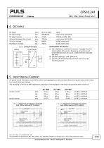
CPS10.241 24V, 10A, SINGLE PHASE INPUT 4. DC-INPUT DC input DC input range DC input current Allowed Voltage L/N to Earth Turn-on voltage Shut-down voltage ±20% continuous operation 110Vdc, at 24V, 10A continuous, IEC 62103 steady state value steady state value Instructions for DC use: a) Use a battery or a similar DC source. A supply from the intermediate DC-bus of a frequency converter is not recommended and can cause a malfunction or damage the unit. b) Connect +pole to L and –pole to N. c) Connect the PE terminal to an earth wire or to the machine ground. 5. INPUT INRUSH CURRENT An active...
Open the catalog to page 6
CPS10.241 24V, 10A, SINGLE PHASE INPUT 6. OUTPUT Output voltage Adjustment range Factory settings Line regulation Load regulation Ripple and noise voltage Output current Output power Overload behaviour Short-circuit current Output capacitance *) guaranteed at clockwise end position of potentiometer ±0.2%, at full load and cold unit 85-300Vac static value, 0A 10A; see Fig. 6-1 20Hz to 20MHz, 50Ohm at 24V, ambient temperature <60°C, see Fig. 6-1 at 24V, ambient temperature <45°C, see Fig. 6-1 at 28V, ambient temperature <60°C, see Fig. 6-1 at 28V, ambient temperature <45°C, see Fig. 6-1 up to at...
Open the catalog to page 7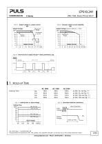
□innefUSIOfU C-Series 24V, 10A, SINGLE PHASE INPUT Fig. 6-1 Output voltage vs. output current, Output Voltage Fig. 6-2 Dynamic output current capability, Output Voltage (dynamic behavior, < 15ms) Output Current Fig. 6-3 Short-circuit on output. Hiccup""75 mode, preliminary, typ. Hold-up Time Fig. 7-1 Hold-up time vs. input voltage Hold-up Time Input Voltage Fig. 7-2 Shut-down behavior, definitions Zero Transition All parameters are specified at 24V, 10A, 230Vac, 25°C ambient and after a 5 minutes run-in time unless otherwise noted.
Open the catalog to page 8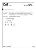
CPS10.241 24V, 10A, SINGLE PHASE INPUT 8. DC-OK RELAY CONTACT This feature monitors the output voltage on the output terminals of a running power supply. Contact closes Contact opens As soon as the output voltage reaches typ. 90% of the adjusted output voltage level. As soon as the output voltage dips more than 10% below the adjusted output voltage. Short dips will be extended to a signal length of 100ms. Dips shorter than 1ms will be ignored. max. 60Vdc 0.3A, 30Vdc 1A, 30Vac 0.5A resistive load min. 1mA at 5Vdc min. permissible load See dielectric strength table in section 18. Contact ratings...
Open the catalog to page 9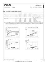
CPS10.241 24V, 10A, SINGLE PHASE INPUT 9. EFFICIENCY AND POWER LOSSES typ. typ. typ. Average efficiency*) Power losses The average efficiency is an assumption for a typical application where the power supply is loaded with 25% of the nominal load for 25% of the time, 50% of the nominal load for another 25% of the time, 75% of the nominal load for another 25% of the time and with 100% of the nominal load for the rest of the time. Fig. 9-1 Efficiency vs. output current at 24V, typ. Fig. 9-2 Losses vs. output current at 24V, typ. Power Losses Output Current Output Current Fig. 9-3 Efficiency vs....
Open the catalog to page 10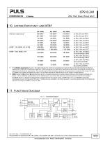
CPS10.241 24V, 10A, SINGLE PHASE INPUT Lifetime expectancy*) The Lifetime expectancy shown in the table indicates the minimum operating hours (service life) and is determined by the lifetime expectancy of the built-in electrolytic capacitors. Lifetime expectancy is specified in operational hours and is calculated according to the capacitor’s manufacturer specification. The manufacturer of the electrolytic capacitors only guarantees a maximum life of up to 15 years (131 400h). Any number exceeding this value is a calculated theoretical lifetime which can be used to compare devices. **) MTBF stands...
Open the catalog to page 11All PULS GmbH catalogs and technical brochures
 MLY10.241
18 Pages
 MLY02.100
18 Pages
 QT40.361
28 Pages
 CD10.242
29 Pages
 XT40.361, XT40.362
21 Pages
 SL20.310
2 Pages
 SL20.300
2 Pages
 ML70.100
2 Pages
 SLR01
SLR012 Pages
 SLR10.100
2 Pages
 SL40.301
2 Pages
 SL40.300
2 Pages
 SL30.300
2 Pages
 SL20.303
2 Pages
 SL20.301
2 Pages
 SL10.309
2 Pages
 SL10.305
4 Pages
 SL10.300
2 Pages
 SL5.300
2 Pages
 SL30.100
2 Pages
 SL20.115
2 Pages
 SL20.113
2 Pages
 SL20.112
2 Pages
 SL20.111
2 Pages
 SL20.110
2 Pages
 SL20.101
2 Pages
 SL20.100
2 Pages
 SL10.106
2 Pages
 SL10.105
2 Pages
 SL10.10
2 Pages
 SL10.104
2 Pages
 SL10.101
2 Pages
 SL10.100
2 Pages
 SL5.105
2 Pages
 SL5.102
2 Pages
 SL5.100
2 Pages
 SL4.100
2 Pages
 SL2.103
2 Pages
 SL2.100
2 Pages
 ML100.200
2 Pages
 ML90.200
2 Pages
 ML100.105
2 Pages
 ML100.102
2 Pages
 ML100.100
2 Pages
 ML95.100
2 Pages
 ML60.121
23 Pages
 ML50.111
2 Pages
 ML50.109
20 Pages
 ML50.105
2 Pages
 ML50.102
2 Pages
 ML50.101
2 Pages
 ML50.100
20 Pages
 ML30.241
23 Pages
 ML30.106
2 Pages
 ML30.102
2 Pages
 ML30.101
2 Pages
 ML30.100
2 Pages
 ML15.241
23 Pages
 ML15.121
23 Pages
 ML15.051
22 Pages
 YRM2.DIODE
19 Pages
 YR80.241
17 Pages
 YR40.241
17 Pages
 YR2.DIODE
19 Pages
 XT40.722
19 Pages
 XT40.721
19 Pages
 XT40.482
20 Pages
 XT40.481
20 Pages
 XT40.362
20 Pages
 XT40.242
20 Pages
 XT40.241
20 Pages
 ZM15.SIDE
2 Pages
 ZM14.SIDE
2 Pages
 ZM13.SIDE
2 Pages
 ZM12.SIDE
2 Pages
 ZM11.SIDE
2 Pages
 ZM2.WALL
3 Pages
 ZM1.WALL
2 Pages
 ZM1.UBC10
2 Pages
 UZS24.100
3 Pages
 UF20.481
13 Pages
 UF20.241
11 Pages
 UZO12.26
2 Pages
 UZO12.07
9 Pages
 UZK12.261
8 Pages
 UZK12.071
9 Pages
 UBC10.241-N1
23 Pages
 UBC10.241
23 Pages
 UB10.245
24 Pages
 UB10.242
21 Pages
 UB10.241
23 Pages
 QT40.481
28 Pages
 QT40.241
28 Pages
 QT20.481
23 Pages
 QT20.361
23 Pages
 QT20.241-C1
23 Pages
 QT20.241
23 Pages
 QTD20.241
22 Pages
 QS10.481-D1
27 Pages
 QS10.241-D1
27 Pages
 QS40.484
28 Pages
 QS40.244
28 Pages
 QS20.481
25 Pages
 QS20.361
25 Pages
 QS20.244
25 Pages
 QS20.241-C1
26 Pages
 QS20.241-A1
26 Pages
 QS20.241
26 Pages
 QS10.481
27 Pages
 QS10.DNET
22 Pages
 QS10.301
26 Pages
 QS5.DNET
21 Pages
 QS5.241-A1
26 Pages
 QS5.241
26 Pages
 QS3.241
25 Pages
 PISA11.CLASS2
19 Pages
 PISA11.206212
23 Pages
 PISA11.203206
23 Pages
 PISA11.410
23 Pages
 PISA11.406
23 Pages
 PISA11.404
23 Pages
 PISA11.403
23 Pages
 PISA11.402
23 Pages
 PISA11.401
23 Pages
 PIC240.241D
21 Pages
 PIC120.241C
21 Pages
 PAS395
14 Pages
 CT10.481
22 Pages
 CT10.241
22 Pages
 CT5.241
21 Pages
 CT5.121
21 Pages
 CS10.481
20 Pages
 CS10.244
21 Pages
 CS10.243
19 Pages
 CS10.242
19 Pages
 CS10.241-S1
20 Pages
 CS10.241
20 Pages
 CS5.244
20 Pages
 CS5.243
19 Pages
 CS5.241-S1
20 Pages
 CS5.241-C1
20 Pages
 CS5.241
20 Pages
 CS3.241
21 Pages
 CPS20.241-C1
26 Pages
 CP10.242
27 Pages
 CD5.243
22 Pages
 CD5.242
22 Pages
 CD5.241-S1
23 Pages
 CD5.241-L1
21 Pages
 CD5.241
22 Pages
 CD5.121
22 Pages
 PIC120.242C
21 Pages
 PIC240.241C
20 Pages
 QS40.361
27 Pages
 QS40.481
28 Pages
 UB20.241
31 Pages
 UZK24.071
9 Pages
 UZK24.121
9 Pages
 UZO24.071
9 Pages
 UZO24.121
9 Pages
 UC10.241
27 Pages
 UC10.242
27 Pages
 YR40.242
17 Pages
 YR40.245
18 Pages

Archived catalogs
 SLZ02
SLZ022 Pages
 SLZ11
SLZ112 Pages
 SLZ12
SLZ122 Pages
 SLZ14
SLZ142 Pages
 FPS300 series
32 Pages
 FPT500 series
35 Pages
 QS10.121
26 Pages
 QS10.241
28 Pages
 QS10.241-A1
27 Pages
 QS10.241-C1
27 Pages
 Selection Guide 2015/2016
25 Pages
 selection guide 2018
31 Pages
 DECENTRALIZED POWER SUPPLIES
9 Pages
 PIANO PIC
2 Pages
 PULS CP
7 Pages
 YR40.482
17 Pages
 YR80.242
17 Pages
 SLA3.100
4 Pages
 SLA4.100
4 Pages
 SLA8.100
4 Pages
 SLA8.300
4 Pages
 SLAD4.100
4 Pages
 SLD2.100
2 Pages
 SLR02
SLR022 Pages
 SLR2.100
2 Pages
 SLR5.100
2 Pages
 SLR10.108
2 Pages
 SLV20.200
4 Pages
 SLZ10-14
2 Pages
 ML60.122
23 Pages
 ML60.241
23 Pages
 ML60.242
23 Pages
 ML120.241
22 Pages
 ML120.244
21 Pages
 ML120.CLASS2
19 Pages
 CP10.121
26 Pages
 PIANO
PIANO5 Pages
 ZM3.WALL
1 Page
 CPS20.481-D1
25 Pages
 CPS20.241-D1
25 Pages
 Selection Guide 2013
19 Pages
 QS40.241, QS40.241-A1
28 Pages
 CPS20.241
25 Pages
 CPS20.361
25 Pages
 CPS20.481
25 Pages
 CPS20.121
25 Pages
 PIC120.241D_2015
22 Pages
 PIC120.241D_2014
21 Pages
 Products 2009-2010
28 Pages
 Products 2007
34 Pages


- DC power supply
- AC/DC power supply
- CE power supply
- Single-output power supply
- Switching power supply
- Power supply for industrial applications
- DC-DC converter
- Circuit breaker
- Power supply with overload protection
- Compact power supply
- DIN rail power supply
- Variable-output power supply
- Single-phase power supply
- Multiple-output power supply
- Regulated power supply
- Industrial UPS
- Three-phase power supply
- Current circuit breaker
- Voltage circuit breaker