RD3
1 /42Pages

RD3
1 /42Pages
Catalog excerpts

Innovative Measurement Electronics RD3 Remote Display User Manual Rev. 2.0
Open the catalog to page 1
Copyright All Rights Reserved. No part of this document may be copied, reproduced, republished, uploaded, posted, transmitted, distributed, stored in or introduced into a retrieval system in any form, or by any means (electronic, mechanical, photocopying, recording or otherwise) whatsoever without prior written permission of PT Ltd. Disclaimer PT Ltd reserves the right to make changes to the products contained in this manual in order to improve design, performance or reliability. The information in this manual is believed to be accurate in all respects at the time of publication, but is subject...
Open the catalog to page 2
Remote Display Installation Manual - Software Version 2.x
Open the catalog to page 3
Remote Display Installation Manual - Software Version 2.x This remote display is a highly visible instrument that is compatible with many other digital weight indicators. There is no setup required as this remote display automatically detects the communications parameters being used by the transmitting device. This manual contains information on the installation of the remote display. CE, FCC and C-tick approved. 1.2. Features The remote display is fitted with an alphanumeric 20mm LCD with super bright LED back lighting display that can be read in all conditions. 1.3. Document Conventions The...
Open the catalog to page 4
Remote Display Installation Manual - Software Version 2.x
Open the catalog to page 5
Remote Display Installation Manual - Software Version 2.x 3.1. General Instrument not to be subject to shock, excessive vibration or extremes of temperature; before or after installation. Inputs are protected against electrical interference, but excessive levels of electro-magnetic radiation and RFI may affect operation. For full EMC or for RFI immunity, termination of the cable shields and correct earthing of the instrument is essential. Instrument is sensitive to excessive electrical noise and should be installed well away from any power or switching circuits. 3.2. Electrical Safety For your...
Open the catalog to page 6
Remote Display Installation Manual - Software Version 2.x 4.1. General Setup Information The following steps are required to set up the remote display. • Inspect instrument to ensure good condition. • Ensure mounting options and connectors are available. • Use connection diagram to wire up power and serial cables as required. • Instrument has built in panel mounting screws. Use the "Panel Drilling Template" provided for hole locations. The panel mounting screws are also used to attach desk/wall brackets or the stainless steel rear housing accessories. • Connect the serial and power cables to...
Open the catalog to page 7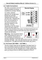
Remote Display Installation Manual - Software Version 2.x 4.3. Cable Connections All cable connections are m using screwless terminals. insulation by at least 10mm. To install, carefully depress the orange lever beside the terminal required and push wire into the hole. Release the lever and pull gently on the wire to ensure it is securely trapped in the terminal. It is not necessary to tin the ends of the wire with solder or to add crimp ferrules to the wires, but these techniques are also compatible with the terminals and may make for a neater job ultimately. Warning: Care should be taken when...
Open the catalog to page 8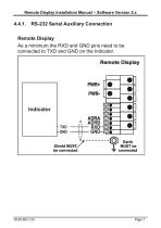
Remote Display Installation Manual – Software Version 2.x RS-232 Serial Auxiliary Connection Remote Display As a minimum the RXD and GND pins need to be connected to TXD and GND on the Indicator.
Open the catalog to page 9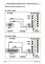
Remote Display Installation Manual – Software Version 2.x Direct Personal Computer Link PC COM 1 (DB9)
Open the catalog to page 10
Remote Display Installation Manual – Software Version 2.x 4.5. Cable Shield Connection and Earthing To obtain full EMC resistance cable shields MUST be connected to the earth lug on the rear of the instrument. Care should be taken when connecting shields to maximise EMC or RFI immunity and minimise earth loops and cross-talk (interference) between instruments. For full EMC or for RFI immunity, termination of the cable shields at the earth lug is very important. The earth lug of the instrument must be separately connected to ground potential via a reliable link. The instrument should only be connected...
Open the catalog to page 11
Remote Display Installation Manual - Software Version 2.x 5.1. Baud (Serial Baud Rate) Baud rate, parity and data bits are automatically detected. The baud rate can be 9600 or 19200. Parity and data bits supported are: 5.2. Delimiters The instrument responds to any string that ends with the following: CRLF (ASCII 013, 010), or ENQ (ASCII 05), or any string that starts with STX (ASCII 02) and ends with ETX (ASCII 03). 5.3. Address The instrument has a default address of 01 however the address can be set to 02 by connecting the TXD output to the DTR input. For most protocols an address of 00 is...
Open the catalog to page 12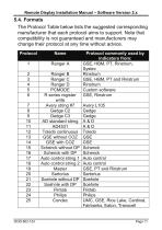
_Remote Display Installation Manual - Software Version 2.x 5.4. Formats The Protocol Table below lists the suggested corresponding manufacturer that each protocol aims to support. Note that compatibility is not guaranteed and manufacturers may change their protocol at any time without advice.
Open the catalog to page 13
_Remote Display Installation Manual - Software Version 2.x
Open the catalog to page 14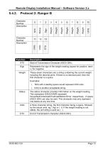
_Remote Display Installation Manual - Software Version 2.x
Open the catalog to page 15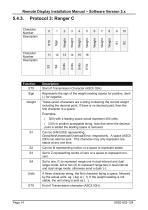
_Remote Display Installation Manual - Software Version 2.x
Open the catalog to page 16
_Remote Display Installation Manual - Software Version 2.x
Open the catalog to page 17
_Remote Display Installation Manual - Software Version 2.x
Open the catalog to page 18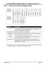
_Remote Display Installation Manual - Software Version 2.x Note: When using this protocol the display timeout is disabled, which means that the message will remain on the display until new data is sent.
Open the catalog to page 19
_Remote Display Installation Manual - Software Version 2.x
Open the catalog to page 20
_Remote Display Installation Manual - Software Version 2.x
Open the catalog to page 21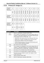
_Remote Display Installation Manual - Software Version 2.x
Open the catalog to page 22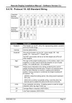
_Remote Display Installation Manual - Software Version 2.x
Open the catalog to page 23
_Remote Display Installation Manual - Software Version 2.x
Open the catalog to page 24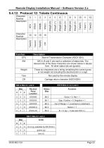
Remote Display Installation Manual - Software Version 2.x
Open the catalog to page 25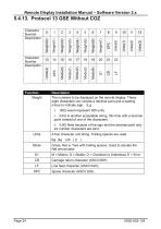
_Remote Display Installation Manual - Software Version 2.x
Open the catalog to page 26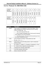
_Remote Display Installation Manual - Software Version 2.x
Open the catalog to page 27All PT Limited catalogs and technical brochures
 Models ASB/AST
2 Pages
 PT100SSB
3 Pages
 PT9011OVL
2 Pages
 PT321
PT3212 Pages
 PT200M/P
4 Pages
 PT100LC
2 Pages
 RD4/5/6
1 Page
 PT252 series
2 Pages
 PT630 series
4 Pages
 PT620
PT6204 Pages
 PT610
PT6104 Pages
 PTASP6-N
1 Page
 PTASP6-E3
1 Page
 HPT02
HPT021 Page
 HPT03
HPT031 Page
 HPT04
HPT041 Page
 PT113
PT1132 Pages
 PT110LC, PT111LC
2 Pages
 PT253
PT2532 Pages
 PT200MB
2 Pages
 PT210
PT2102 Pages
 Onboard Vehicle
2 Pages
 PTSSP6-G Brochure
1 Page
 PTASP6-W Brochure
1 Page
 PTSSP6-E Brochure
1 Page
 PTSSP6-F Brochure
1 Page
 PTSSP6-GW Brochure
1 Page
 PTSSP6-N Brochure
1 Page
 PTSSP6-Q Brochure
1 Page
 SLSP Brochure
1 Page
 Shackle Brochure
1 Page
 SSC Brochure
2 Pages
 ST Brochure
2 Pages
 Swivel Feet Guide
1 Page
 PT100SA Surge Arrestors
2 Pages
 Load & Shackle Pins
1 Page
 HPC Compression IP67 sealed
2 Pages
 HPC Compression IP68
2 Pages
 LCSST 'S' Type
1 Page
 PT8000 Bending Beam
2 Pages
 LCSB Shearbeam
1 Page
 PT5100 Shearbeam S/S
1 Page
 LS Shearbeam
2 Pages
 PT5000 Shearbeam
2 Pages
 PT200MI Popular Panel Mount
2 Pages
 LPX
LPX2 Pages
 LPCS
LPCS1 Page
 LPCH
LPCH2 Pages
 PSB
PSB2 Pages
 LPC
LPC2 Pages
 Model ST
2 Pages
 ASB & AST Brochure
2 Pages


Archived catalogs
 Load cell & Accessory catalogue
44 Pages
- Electrical cable
- Data connector
- Force sensor
- Surge protector
- Tension/compression force transducer
- Steel load cell
- Socket electrical connector
- Screw-in connector
- Strain gauge force sensor
- Stainless steel force transducer
- Electrical data cable
- Weighing force transducer
- Beam type force sensor
- Straight connector
- Cable connector
- Compression force transducer
- Digital weight indicator-transmitter
- Screw connector