QPV1
1 /12Pages

QPV1
1 /12Pages
Catalog excerpts

THE INSIDE STORY OF THE QPV OR MPV: QPV2 or MPV2 Accepts Feedback Signal from an External Sensor Access Hole Permits Field Adjustments QPV has an IP65 Enclosure Allows it to Endure the Elements and be Washed Down Without Harm Electronic Control Circuit Pressure Zero and Pressure Span Adjustments Available in a Wide Range of Electrical Control Inputs and Analog Outputs Adjustable Hysteresis Band & System Stability Many Connector Options Proportional Inlet Valve Mounts in any Position Exhaust Valve Multiple Mounting Brackets Available 1/8” NPT Supply Port QPV Weights 1.02 LBS (0.5 KG) MPV Weights...
Open the catalog to page 2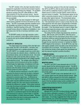
The QPV member of the ultra high resolution family is designed for applications where the environment requires that the internal components are protected. The anodized aluminum housing of the QPV offers NEMA 4 or IP65 rated protection for this fully enclosed version. Several different mounting configurations and mounting accessories are available. The MPV version has been designed for OEM applications where protection from the environment is not necessary. The MPV incorporates extremely versatile mounting capabilities that allows for DIN rail mounting, panel mounting or manifold mounting of the...
Open the catalog to page 3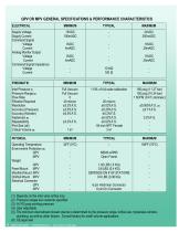
QPV OR MPV GENERAL SPECIFICATIONS & PERFORMANCE CHARACTERISTICS ELECTRICAL Supply Voltage Supply Current Command Signal Voltage Current Analog Monitor Output Voltage Current Command Signal Impedance Voltage Current 110% of full scale calibration 20 micron ±0.02%F.S. ±0.25%F.S. ±0.3%F.S. ±0.02%F.S. ±0.02%F.S. 1/8 inch NPT Female 3 in³ Operating Temperature Environment Protection (6) QPV MPV Weight QPV Panel Mount MPV Manifold Mount MPV DinRail Mount MPV Electrical Connector QPV MPV NEMA 4/IP65 Open Frame 6 pin Hirshman Connector 6 pin Din Connector Inlet Pressure (1) Pressure Range (2) Flow Rate...
Open the catalog to page 4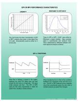
QPV OR MPV PERFORMANCE CHARACTERISTICS RESPONSE TO STEP INPUT LINEARITY LINEARITY RESPONSE TO STEP INPUT Command [Volts] This chart shows the linear characteristics of QPV or MPV products when given a ramp signal from 0-10 volts. Characteristics would be similar for 420 mA units. Times for QPV or MPV (0.040” valve orifice) to fill/exhaust a closed chamber. Step command signal is superimposed over pressure trace. Time is determined by difference between command signal and pressure achieved. When flow or leakage is present in the system, traditional two valve I/P’s bleed down and then actuate the...
Open the catalog to page 5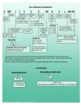
SERIES DIGITAL DISPLAY COMMAND INPUT CONTAINER T = IMPACT ALUM. 1 = SINGLE SENSOR 2 = TWO SENSOR MONITOR SIGNAL INLET VALVE ORIFICE SIZE ¹ E = 0-10VDC C = 4-20mA Sinking S = 4-20mA Sourcing MAXIMUM CALIBRATED RANGE VAC-150 psi* D = Digital display BLANK = No display Cx REQUIRED FOR ALL QPV VALVES Factory determined based on the specifications of the application BLEED ORIFICE ² SPECIAL OPTIONS* L = BLEED ORIFICE BLANK = NO ORIFICE S86-100 = ABSOLUTE SENSOR, 100 PSIA RATING * Consult Factory for More Special Options * Check special options for Pressure ranges not starting at “0” psi ¹ Inlet valves...
Open the catalog to page 6
1 = SINGLE SENSOR 2 = TWO SENSOR M = MANIFOLD MOUNT P = PANEL MOUNT D = DIN RAIL MOUNT INLET VALVE ORIFICE SIZE ¹ MOUNTING METHODS MONITOR SIGNAL MAXIMUM CALIBRATED RANGE EXAMPLES 100 = 0-100 PSI 001 = 0-1 PSI N20= atm-20 in Hg Vacuum * Pressure ranges not starting at “0” psig are available. Consult factory for ordering information. L = BLEED ORIFICE BLANK = NO ORIFICE FACTORY DETERMINED (Depends on the application flow & pressure specs) S17 = 0-5VDC COMMAND * Consult Factory for More Special Options REQUIRED FOR ALL MPV VALVES Factory determined based on the specifications of the application...
Open the catalog to page 7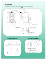
QPV DIMENSIONS DIMENSIONS ARE FOR REFERENCE USE ONLY. DIMENSIONS ARE IN INCHES (MILLIMETERS) BRQB30105E * PROPORTION-AIR * LET’S TALK 317-335-2602 BRQPV-MPV0305E * PROPORTION-AIR * LET’S TALK 317-335-2602
Open the catalog to page 8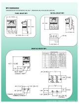
MPV DIMENSIONS DIMENSIONS ARE FOR REFERENCE USE ONLY. DIMENSIONS ARE IN INCHES (MILLIMETERS) LET’S TALK 317-335-2602 * PROPORTION-AIR * BRQB30105E LET’S TALK 317-335-2602 * PROPORTION-AIR * BRQPV-MPV0305E
Open the catalog to page 9
QPV OR MPV TYPICAL APPLICATIONS LEAK TESTING (METHOD 1) Controller DS - Series Pressure Transducer Part Under Test Media Supply A Proportion-Air control valve can precisely control pressure to leak test parts. Once the test part is pressurized by the QPV1, the controller closes the shutoff valve. The DS-Series pressure transducer senses pressure in the part under test. Leak decay is recorded by the controller. Once the test is completed, the controller opens the shutoff valve and pressure is relieved through the QPV1. LEAK TESTING (METHOD 2) Controller Article under Test Flow Transducer Pressure...
Open the catalog to page 10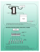
In this application a QP E tro-pneumatic control valve is c ontrolling pressure of air over V1 lec flux, thus controlling the amount of flux whic h being dispensed. Why a QPV1? B ecause this is a low flow, low pressure applic ation that c an be maintained using the QP V1. HIGH RESOLUTION FORCE CONTROL USING AIR-PEL CYLINDERS Controller PLC, PID, Potentiometer, etc Manifold mount MPV1 Air Supply Air-Pel Cylinders Part Under Test In this application, 7- MPV1's mounted on a SBM-7 sub-base manifold are controlling the force on spring loaded Air-Pel cylinders to test the breaking point of small automotive...
Open the catalog to page 11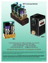
MPV’s Sub-based Manifold
Open the catalog to page 12All Proportion-Air catalogs and technical brochures
 High Pressure
4 Pages
 ISF1
ISF18 Pages
 DS
DS4 Pages
 SELECT 6 POWER SUPPLY
2 Pages
 RQ-02
RQ-022 Pages
 RG873V
2 Pages
 RM-SERIES VOLUME BOOSTERS
2 Pages
 PM-4 DIGITAL INDICATOR
1 Page
 PM-3 DIGITAL INDICATOR
1 Page
 GP1 / GP2
4 Pages
 F-SERIES
8 Pages
 F-SERIES FLOW CONTROLLER
12 Pages
 DC2
DC22 Pages
 DQB1
DQB18 Pages
 MPV1
MPV112 Pages
 R-Series Volume Boosters
2 Pages
 RG0003 WATER REGULATOR
1 Page
 Product Catalogue
24 Pages
 PSR Series
4 Pages
 Air flow control
12 Pages
 BB2/PSR & QB2/PSR
8 Pages
 QB3H
QB3H2 Pages
 QB4 PRESSURE CONTROL VALVE
5 Pages
 US1 ULTRASONIC SENSOR
1 Page
 PS300 POWER SUPPLY
1 Page
 V ELECTRO-PNEU. FLOW VALVE
4 Pages


