Catalog excerpts

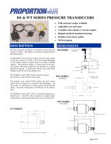
DS & WT SERIES PRESSURE TRANSDUCERS ♦ Wide pressure ranges available Adjustable zero and span Available with voltage or current outputs Rugged anodized aluminum housing Stainless steel sensor option DS series pressure transducers accurately measure pressure of gases or fluids. The output is an electrical signal based on the measurement. Conditioning of the electrical signal from the strain gauge sensor gives either 0-10 VDC or 4-20 mA output depending on the model ordered (consult factory for other available outputs). The electrical output is a linear ratio of the pressure sensed. DS series transducers are enclosed in a rugged aluminum housing. A strain relief protects the wiring from damage caused by excessive pulling force. The standard version (DS) measures pressure using a piezoresistive semiconductor sensor chip. The stainless steel version (DST) utilizes the same silicon etched device mounted on a stainless steel diaphragm. On these units, no elastomers or o-rings contact the pressurized media. All media wetted parts are ANSI type 316L stainless steel. The NEMA4 version (WT series) is electrically identical to the DS series. The WT series is housed in a slightly larger canister that is sealed against fluid spray from any direction. ELECTRICAL CONNECTOR— USER SPECIFIED
Open the catalog to page 1
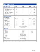
SPECIFICATIONS ELECTRICAL Supply Voltage Supply Current DSZ, DSX, DSTX, DSTVX, DSY, DSTY, DSTVY, WTE DSI, DSTI, DSTVI, WTI Analog Output DSX, DSTX, DSTVX, DSY, DSTY, DSTVY, WTE DSI, DSTI, DSTVI, WTI DSZ +/-0.2 +/-0.5 — Zero and span adjustable <1% over specified tem. Range (0-50ºC , 122º F ) PERFORMANCE* Pressure Ranges* DS & WT Series: DST Series: Response Time: Repeatability DS & WT Series: DST Series: Accuracy DS & WT Series: DST Series: Operation Temp.: Calibration Temp. Effect: PHYSICAL Weight WT Series: DS Series: DST Series: Materials Seals: Housing: Fitting: Media DS & WT Series:...
Open the catalog to page 2
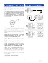
CALIBRATION PROCEDURE ELECTRICAL CONNECTION The WT, DS & DST series pressure transducers are factory calibrated. Should further calibration be required, please follow these procedures. Two calibration potentiometers on the pressure transducer set the overall zero and span points. They are located on the back of the transducer recessed in two holes.¹ (See figure 1 for location) These adjustments are set by the factory and covered with metallic tape. This metal tape may be removed to recalibrate the unit.¹ Figure 1 *You must have a good understanding of what the span and zero set adjustments...
Open the catalog to page 3
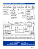
DS & WT SERIES ORDERING INFORMATION DS Series Units Available Electrical Connection Blank = Standard construction V = Vacuum T = Stainless steel TV = Vacuum stainless steel. X = 3 wire 0-10VDC Voltage output I = 2 wire 4-20 mA Current output Y = Mini 3 pin plug For all BB2 voltage command units & all QB2T S305 units Z = Mini 3 pin for all BB2 current command units (S191 equipped units utilize DSY) E = 3 wire 0-10VDC Voltage output I = 2 wire 4-20 mA Current output A = 3 Pin, 3 FT female molded cord B = 2 Wire flying leads (I units only) (18”) C = 3 Wire flying leads (18”) D = 3 Pin male...
Open the catalog to page 4All Proportion-Air catalogs and technical brochures
-
High Pressure
4 Pages
-
ISF1
8 Pages
-
DS
4 Pages
-
SELECT 6 POWER SUPPLY
2 Pages
-
RQ-02
2 Pages
-
RG873V
2 Pages
-
RM-SERIES VOLUME BOOSTERS
2 Pages
-
PM-4 DIGITAL INDICATOR
1 Pages
-
PM-3 DIGITAL INDICATOR
1 Pages
-
GP1 / GP2
4 Pages
-
FPP SERIES IN-LINE FILTER
1 Pages
-
F-SERIES
8 Pages
-
F-SERIES FLOW CONTROLLER
12 Pages
-
DC2
2 Pages
-
DQB1
8 Pages
-
QPV1
12 Pages
-
MPV1
12 Pages
-
R-Series Volume Boosters
2 Pages
-
RG0003 WATER REGULATOR
1 Pages
-
Product Catalogue
24 Pages
-
PSR Series
4 Pages
-
Air flow control
12 Pages
-
BB2/PSR & QB2/PSR
8 Pages
-
QB3H
2 Pages
-
QB4 PRESSURE CONTROL VALVE
5 Pages
-
US1 ULTRASONIC SENSOR
1 Pages
-
PS300 POWER SUPPLY
1 Pages
-
V ELECTRO-PNEU. FLOW VALVE
4 Pages


