- Catalogs
- Promstahl WorldWide
- Mechanical Dock Shelter PMV - Installation manual
- Company
- Products
- Catalogs
- News & Trends
- Exhibitions
Mechanical Dock Shelter PMV - Installation manual
1 /10Pages

Mechanical Dock Shelter PMV - Installation manual
1 /10Pages
Catalog excerpts

Mechanical dock shelter PMV Installation manual Technical modifications reserved
Open the catalog to page 1
Mechanical dock shelter PMV Technical modifications reserved
Open the catalog to page 2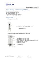
Mechanical dock shelter PMV 1. Scope of supply – mechanical sealing gate, PMV-type: Frame component, left - set (1 pc) Frame components, right - set (1 pc) Top gate component - set (1 pc) Sheet-metal screw 5.5x16 - DIN 7049 (4 pcs) Fixing elements appropriate for wall fixation: 2. Wall assembly 2.1 Fixing to a concrete wall 1 expanding anchor W-FA M10x95 (WÜRTH) (11 pcs) (Blind hole Ø10 x 70) 2.2 Fixing to an aerated concrete wall (wall thickness – max 300 mm) M8 hexagon nut – ISO 7040 (11 pcs) M8 hexagon nut – DIN 1587 (11 pcs) M8 x L threaded rod (L = wall thickness + 50 mm), DIN...
Open the catalog to page 3
Mechanical dock shelter PMV 2.3 Fixing to an insulation wall (wall thickness: 60 mm, 80 mm, 100 mm) M8 hexagon nut - DIN 7040 (11 pcs) M8 hexagon nut - DIN 1587 (11 pcs) M8x threaded rod (L = wall thickness + 50 mm), DIN 975 (11 pcs) Washer Ø8.4 - DIN 125 (11 pcs) Plate D100 x 4 (11 pcs) Spacer tube Ø13.5x2.3xL (L = wall thickness - 5 mm), DIN 2458 (11 pcs) (Through hole Ø14) 2.4 Fixing to a wall – smooth sheet (thickness: 3 mm) 1 Sheet-metal screw - kombi 9.5x38 C, DIN 7976 (11 pcs) (Through hole Ø8.7) 2.5 Fixing to a wall – smooth sheet (thickness: <3 mm) Screw M8x45 – ISO 4014 (11 pcs) Washer...
Open the catalog to page 4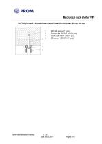
Mechanical dock shelter PMV 2.6 Fixing to a wall – insulated concrete wall (insulation thickness:100 mm, 200 mm) Technical modifications reserved KSD M8 anchor (11 pcs) Spacer tube Ø13.5x2.3xL (11 pcs) Washer Ø8.4 DIN 125 (11 pcs) M8 screw – ISO 4014 (11 pcs)
Open the catalog to page 5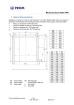
Mechanical dock shelter PMV3. Holes for fixing components Depending on the type of a wall to which the gate is to be fixed, different fixation points are required, in accordance with the drawing. The whole fixation surface of the gate must be compact, smooth and durable. • Fixing to a concrete wall - 010x70 blind hole • Fixing to an aerated concrete wall - 010 through hole • Fixing to an insulation wall - 014 through hole • Fixing to a smooth sheet wall - 08.7 through hole MH Mounting height (recommended = 4500 mm) C Door height Technical modifications reserved v: 2.0.0
Open the catalog to page 6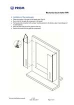
Mechanical dock shelter PMV 4. Installation of the sealing gate Determine position of the gate on the facade (see: Page 4). Bore a hole for the gate side component in the facade. Put the gate side component with a proper mounting element to the facade, adjust it accordingly and fix with fasteners. Mount the other side part of the gate the same way. Remove the hooks from the gate side components. Technical modifications reserved
Open the catalog to page 7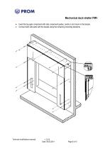
Mechanical dock shelter PMV Insert the top gate component with side component guides, centre it and mount in the facade. Connect both side parts with the facade using the remaining mounting elements. Technical modifications reserved
Open the catalog to page 8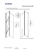
Mechanical dock shelter PMV Connect the tension spring with the chain. Connect the side cushion with the front and rear profiles using three sheet-metal screws. Presentation of the component – before installation Technical modifications reserved
Open the catalog to page 9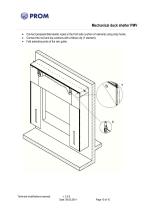
Mechanical dock shelter PMV Connect preassembled elastic ropes to the front side cushion (X element) using snap hooks. Connect the roof and top cushions with a Minax clip (Y element). Fold extending ends of the rain gutter. Technical modifications reserved
Open the catalog to page 10All Promstahl WorldWide catalogs and technical brochures
 Imagefolder
8 Pages
 LED Dock Lights
1 Page
 Distribution Book of PromSTAHL
852 Pages
 Sectional overhead doors
56 Pages
 CATALOG
36 Pages


